The speed input range of the Advance HC400 marine gearbox is 1000-1800 RPM, with engine input power from 342 kW to 595.8 kW. the center distance is 264 mm, the reduction ratio range is 1.50-4.94, the transmission capacity range is 0.190-0.331 kW/RPM, the rated propeller thrust is 82 KN, and the input shaft is in the train Opposite to the output shaft.
Advance HC400 marine gearbox is composed of transmission shaft, output coupling, input coupling, oil pressure gauge, oil Filter, control system, oil pump and other important components.
Advance HC400 marine gearboxes provides three types of control system which are push-pull flexible shaft, electric control and pneumatic control for customers to choose. To meet the different requirement of coupling with different engine brand and models, Advance HC400 marine gearboxes provide different SAE size coupling and housing including SAE 0 1, flywheel SAE 18 16 14 is available……
All of our Advance 400 series marine gearbox can provide CCS classification certificate, some of series can provide international classifications with extra costs which mainly including French BV, British LR, American ABS, Japanese NK , Norway DNV-GL, Russia RS, South Korea KR, Italy RINA and other classification societies.
Advantages Of Advance HC400 Marine Gearbox Parts
Advanced design and sophisticated manufacturing to adapt to various harsh working conditions! High-strength parts, strong ability to work under heavy loads.
Cylinder block and cylinder head adopt integrated design. The occurrence of engine water leakage and oil leakage is prevented, and the parts are about 40% less than other similar engines. The failure rate is greatly reduced.
Using forged steel camshaft and crankshaft, high-strength cylinder block design, multiple parts cast on the cylinder block, high rigidity, high pressure resistance, good reliability, and longer service life.
The cylinder bore adopts a platform mesh honing design. The perfect geometric structure effectively prevents oil leakage, and the use of advanced technology such as new piston ring components and gasket crimping and molding reduces oil loss.
The five key systems of the electronically controlled engine are all developed by DCEC, and have been applied and verified in different fields around the world to ensure the excellent economy and reliability of the product.
By optimizing the control strategy and combining with the actual operating conditions of the equipment, the fuel economy can be further improved.
Technical Specifications
| Gearbox Model: | HC400 |
| Input Speed: | 1000-1800 RPM |
| Power: | 342-595.8 kW @ 1800 RPM |
| Center Distance: | 264 mm |
| Trans.Capacity: | 0.19-0.331 kW / RPM |
| Reduction Ratio: | 1.5-4.61 |
| Rated Thrust: | 82 kN |
| Dimension: | 641 mm * 1010 mm * 890 mm |
| Net Weight: | 820 kg |
| Lead Time: | 15-30 Working Days |
| Payment Terms: | T/T ,L/C |

Search by Part No. or Part Name
Click Kit Name to Check Part List
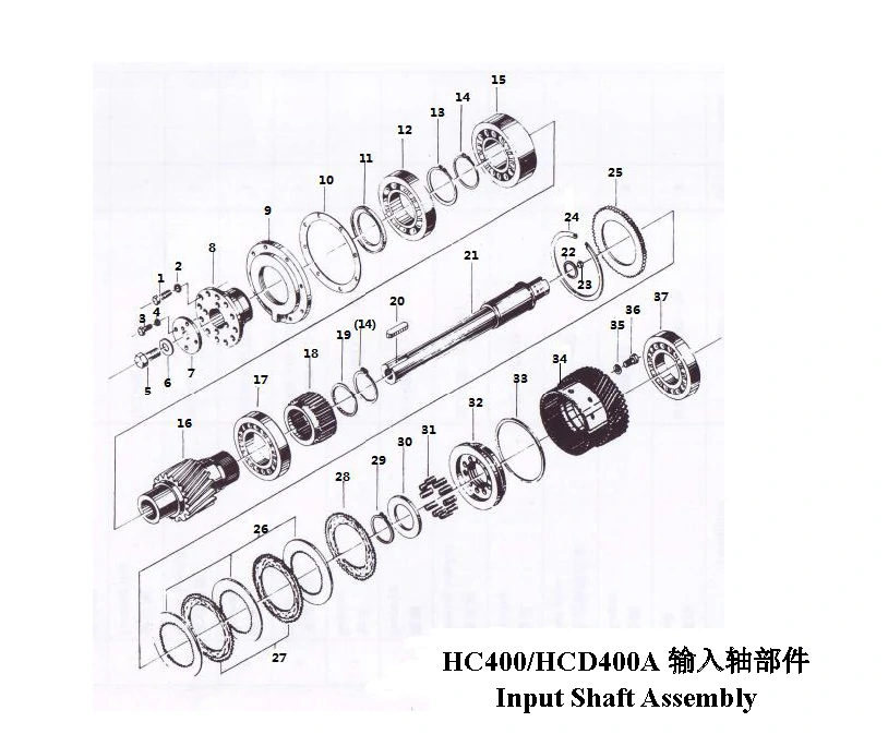
- Input Shaft Assembly
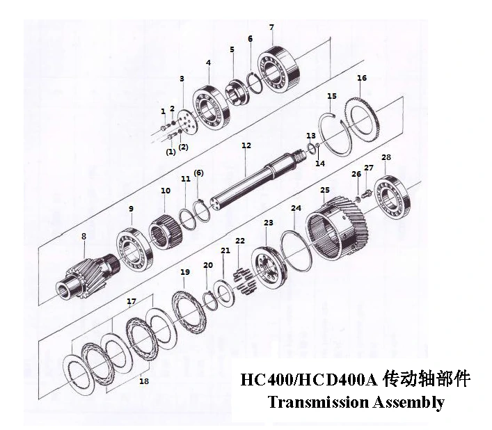
- Transmission Shaft Assembly
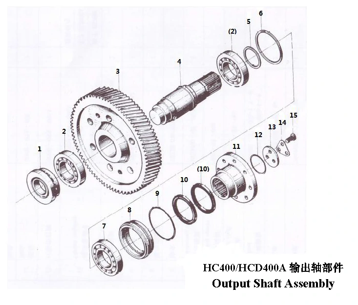
- Output Shaft Assembly
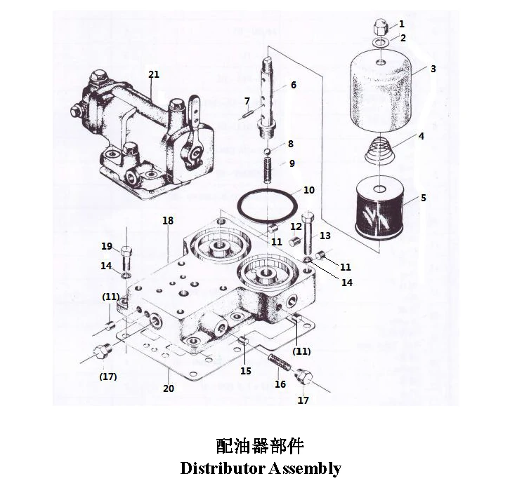
- Distributor Assembly
- Input Coupling Assembly
- Housing Assembly
- Pipe-Type Cooler
No. | Part No. | Part Name | Qty. | Remarks |
| 1 | GB/T5783 – 2000 M14x50 | Bolt | 12 | / |
| 2 | GB/T93 – 1987 14 | Washer | 12 | / |
| 3 | GB/T5783 – 2000 M12x30 | Bolt | 4 | / |
| 4 | GB/T93 – 1987 12 | Washer | 4 | / |
| 5 | GB/T5783 – 2000 M24x50 | Bolt | 1 | / |
| 6 | GB/T856 – 1988 24 | Washer | 1 | / |
| 7 | T300 – 01 – 001 | Plate | 1 | / |
| 8 | HCD400 – 01 – 001 | Input coupling | 1 | / |
| 9 | HCD400 – 01 – 003 | Front end cover | 1 | / |
| 10 | HCD400 – 01 – 002 | Gasket | 1 | / |
| 11 | HCD400 – 01 – 004 | Splashing pan | 1 | / |
| 12 | GB/T276 – 1994 6222 | Bearing | 1 | / |
| 13 | GB/T894.1 – 1986 110 | Snap ring | 1 | / |
| 14 | GB/T894.1 – 1986 95 | Snap ring | 2 | / |
| 15 | GB/T288 – 1994 22319CA/W33 | Bearing | 1 | / |
| 16 | HC400 – 01 – 001/1.5 | Pinion | 1 | z = 34, i = 1.50 |
| 17 | HC400 – 01 – 001/1.77 | Pinion | 1 | z = 30, i = 1.77 |
| 18 | HC400 – 01 – 001/2 | Pinion | 1 | z = 28, i = 2.04 |
| 19 | HC400 – 01 – 001/2.5 | Pinion | 1 | z = 24, i = 2.50 |
| 20 | HC400 – 01 – 001/2.86 | Pinion | 1 | z = 22, i = 2.86 |
| 21 | HCD400 – 01 – 005/4 | Pinion | 1 | z = 21, i = 3.00 |
| 22 | HCD400 – 01 – 005/4.7 | Pinion | 1 | z = 20, i = 3.25 |
| 23 | HC400 – 01 – 001/3.33 | Pinion | 1 | z = 21, i = 3.33 |
| 24 | HCD400 – 01 – 005/6 | Pinion | 1 | z = 19, i = 3.42 |
| 25 | HC400 – 01X – 101/4.61 | Pinion | 1 | z = 18, i = 4.06 |
| 26 | HC400 – 01X – 101/4.94 | Pinion | 1 | z = 18, i = 4.61 |
| 27 | HCD400 – 01 – 005/4 | Pinion | 1 | z = 17, i = 4.94 |
| 28 | HCD400 – 01 – 005/4.3 | Pinion | 1 | z = 23, i = 3.96 |
| 29 | HCD400 – 01 – 005/4.5 | Pinion | 1 | z = 18, i = 4.33 |
| 30 | HCD400 – 01 – 005/4.76 | Pinion | 1 | z = 21, i = 4.43 |
| 31 | HCD400 – 01 – 005/4.7 | Pinion | 1 | z = 21, i = 4.48 |
| 32 | HCD400 – 01 – 005/5 | Pinion | 1 | z = 20, i = 4.70 |
| 33 | HCD400 – 01 – 005/5.5 | Pinion | 1 | z = 19, i = 5.00 |
| 34 | HCD400 – 01 – 005/5.7 | Pinion | 1 | z = 19, i = 5.53 |
| 35 | HCD400 – 01 – 005/6 | Pinion | 1 | z = 17, i = 5.71 |
| 36 | GB/T283 – 2007 N222EKM | Bearing | 1 | / |
| 37 | HCD400 – 01 – 010B | Clutch bracket | 1 | / |
| 38 | HCD400 – 01 – 011 | Locking ring | 1 | / |
| 39 | GB/T1096 – 2003 C20x12x80 | Key | 1 | / |
| 40 | HCD400 – 01 – 006 | Input shaft | 1 | / |
| 41 | 300 – 01 – 016 | Sealing ring | 2 | / |
| 42 | Q21 – 14 φ7×9 | Plug | 1 | / |
| 43 | HCD400 – 01 – 008 | Snap ring | 1 | / |
| 44 | HCD400 – 01 – 009 | Toothed ring | 1 | / |
| 45 | 300 – 01 – 010 | Internal Disc | 8 | / |
| 46 | 300 – 01 – 009A | Outernal Disc | 7 | / |
| 47 | HCD400 – 01 – 012 | Single – face frictional disc | 1 | / |
| 48 | GB/T894.1 – 1986 80 | Snap ring | 1 | / |
| 49 | HCD400 – 01 – 013 | Spring cup | 1 | / |
| 50 | HC600A – 01 – 009A | Spring | 12 | / |
| 51 | HCD400 – 01 – 014A | Piston | 1 | / |
| 52 | 300 – 01 – 012 | Piston ring | 1 | / |
| 53 | HCD400 – 01 – 007 | Left – hand gear | 1 | / |
| 54 | Q20 – 03A 10 | Washer | 2 | / |
| 55 | GB/T70.1 – 2000 M10x25 copperize | Screw | 2 | / |
| 56 | GB/T283 – 2007 NJ222EM | Bearing | 1 | / |
| ——END—— | ||||
No. | Part No. | Part Name | Qty. | Remarks |
| 1 | GB/T5783 – 2000 M12×30 | Bolt | 8 | / |
| 2 | GB/T93 – 1987 12 | Washer | 8 | / |
| 3 | 300 – 02 – 002 | End plate | 1 | / |
| 4 | GB/T276 – 1994 6222 | Bearing | 1 | / |
| 5 | HCD400 – 02 – 001 | Bearing bracket | 1 | / |
| 6 | GB/T894.1 – 1986 95 | Snap ring | 2 | / |
| 7 | GB/T288 – 1994 22319CA/W33 | Bearing | 1 | / |
| 8 | HC400 – 01 – 001/1.5 | Pinion | 1 | z = 34, i = 1.50 |
| 9 | HC400 – 01 – 001/1.77 | Pinion | 1 | z = 30, i = 1.77 |
| 10 | HC400 – 01 – 001/2 | Pinion | 1 | z = 28, i = 2.04 |
| 11 | HC400 – 01 – 001/2.5 | Pinion | 1 | z = 24, i = 2.50 |
| 12 | HC400 – 01 – 001/2.86 | Pinion | 1 | z = 22, i = 2.86 |
| 13 | HCD400 – 01 – 005/4 | Pinion | 1 | z = 21, i = 3.00 |
| 14 | HCD400 – 01 – 005/4.7 | Pinion | 1 | z = 20, i = 3.25 |
| 15 | HC400 – 01 – 001/3.33 | Pinion | 1 | z = 21, i = 3.33 |
| 16 | HCD400 – 01 – 005/6 | Pinion | 1 | z = 19, i = 3.42 |
| 17 | HC400 – 01X – 101/4.61 | Pinion | 1 | z = 18, i = 4.06 |
| 18 | HC400 – 01X – 101/4.94 | Pinion | 1 | z = 18, i = 4.61 |
| 19 | HCD400 – 01 – 005/4 | Pinion | 1 | z = 17, i = 4.94 |
| 20 | HCD400 – 01 – 005/4.3 | Pinion | 1 | z = 23, i = 3.96 |
| 21 | HCD400 – 01 – 005/4.5 | Pinion | 1 | z = 18, i = 4.33 |
| 22 | HCD400 – 01 – 005/4.76 | Pinion | 1 | z = 21, i = 4.43 |
| 23 | HCD400 – 01 – 005/4.7 | Pinion | 1 | z = 21, i = 4.48 |
| 24 | HCD400 – 01 – 005/5 | Pinion | 1 | z = 20, i = 4.70 |
| 25 | HCD400 – 01 – 005/5.5 | Pinion | 1 | z = 19, i = 5.00 |
| 26 | HCD400 – 01 – 005/5.7 | Pinion | 1 | z = 19, i = 5.53 |
| 27 | HCD400 – 01 – 005/6 | Pinion | 1 | z = 17, i = 5.71 |
| 28 | GB/T283 – 2007 N222EKM | Bearing | 1 | / |
| 29 | HCD400 – 01 – 010B | Clutch bracket | 1 | / |
| 30 | HCD400 – 01 – 011 | Locking ring | 1 | / |
| 31 | HCD400 – 02 – 002 | Transmission shaft | 1 | / |
| 32 | 300 – 01 – 016 | Sealing ring | 2 | / |
| 33 | Q21 – 14 φ7×9 | Plug | 1 | / |
| 34 | HCD400 – 01 – 008 | Snap ring | 1 | / |
| 35 | HCD400 – 01 – 009 | Toothed ring | 1 | / |
| 36 | 300 – 01 – 010 | Internal Disc | 8 | / |
| 37 | 300 – 01 – 009A | Outernal Disc | 7 | / |
| 38 | HCD400 – 01 – 012 | Single – face frictional disc | 1 | / |
| 39 | GB/T894.1 – 1986 80 | Snap ring | 1 | / |
| 40 | HCD400 – 01 – 013 | Spring cup | 1 | / |
| 41 | HC600A – 01 – 009A | Spring | 12 | / |
| 42 | HCD400 – 01 – 014A | Piston | 1 | / |
| 43 | 300 – 01 – 012 | Piston ring | 1 | / |
| 44 | HCD400 – 02 – 003 | Right – hand gear | 1 | / |
| 45 | Q20 – 03A 10 | Washer | 2 | / |
| 46 | GB/T70.1 – 2000 M10×25 copperize | Screw | 2 | / |
| 47 | GB/T283 – 2007 NJ222EM | Bearing | 1 | / |
| ——END—— | ||||
No. | Part No. | Part Name | Qty. | Remarks |
| 1 | GB/T5859 – 1994 29418E | Bearing | 1 | / |
| 2 | GB/T283 – 2007 NJ222EM | Bearing | 2 | / |
| 3 | HC400 – 03 – 001/1.5 | Wheel | 1 | z = 51, i = 1.50 |
| 4 | HC400 – 03 – 001/1.77 | Wheel | 1 | z = 53, i = 1.77 |
| 5 | HC400 – 03 – 001/2 | Wheel | 1 | z = 57, i = 2.04 |
| 6 | HC400 – 03 – 001/2.5 | Wheel | 1 | z = 60, i = 2.50 |
| 7 | HC400 – 03 – 001/2.86 | Wheel | 1 | z = 63, i = 2.86 |
| 8 | HC400 – 03 – 001/3 | Wheel | 1 | z = 63, i = 3.00 |
| 9 | HC400 – 03 – 001/3.25 | Wheel | 1 | z = 65, i = 3.25 |
| 10 | HC400 – 03 – 001/3.33 | Wheel | 1 | z = 70, i = 3.33 |
| 11 | HC400 – 03 – 001/3.42 | Wheel | 1 | z = 65, i = 3.42 |
| 12 | HC400 – 03 – 001/4 | Wheel | 1 | z = 73, i = 4.06 |
| 13 | HC400 – 03 – 001/4.61 | Wheel | 1 | z = 83, i = 4.61 |
| 14 | HC400 – 03 – 001/4.94 | Wheel | 1 | z = 84, i = 4.94 |
| 15 | HCD400 – 03 – 002/4 | Wheel | 1 | z = 91, i = 3.96 |
| 16 | HCD400 – 03 – 002/4.3 | Wheel | 1 | z = 78, i = 4.33 |
| 17 | HCD400 – 03 – 002/4.5 | Wheel | 1 | z = 93, i = 4.43 |
| 18 | HCD400 – 03 – 002/4.76 | Wheel | 1 | z = 94, i = 4.48 |
| 19 | HCD400 – 03 – 002/4.7 | Wheel | 1 | z = 94, i = 4.70 |
| 20 | HCD400 – 03 – 002/5 | Wheel | 1 | z = 95, i = 5.00 |
| 21 | HCD400 – 03 – 002/5.5 | Wheel | 1 | z = 105, i = 5.53 |
| 22 | HCD400 – 03 – 002/5.7 | Wheel | 1 | z = 97, i = 5.71 |
| 23 | HCD400 – 03 – 002/6 | Wheel | 1 | z = 106, i = 5.89 |
| 24 | HCD400 – 03 – 001A | Output shaft | 1 | / |
| 25 | 300 – 03 – 004 | Bearing spacer | 1 | / |
| 26 | HCD400 – 03 – 003 | Spacer | 1 | / |
| 27 | GB/T292 – 1994 7222ACM | Bearing | 1 | / |
| 28 | HC400 – 03 – 002 | End cover | 1 | / |
| 29 | GB/T1235 – 1976 200×5.7 | “O” ring | 1 | / |
| 30 | GB/T13871.1 – 2007 FB140x170x15 | Lip – type packing | 2 | / |
| 31 | HC400 – 03 – 003 | Output coupling | 1 | / |
| 32 | D300 – 03A – 005A | “O” ring | 1 | / |
| 33 | D300 – 03A – 008A | Plate | 1 | / |
| 34 | D300 – 03A – 007A | Locking washer | 1 | / |
| 35 | GB/T5783 – 2000 M24x50 | Bolt | 3 | / |
| ——END—— | ||||
No. | Part No. | Part Name | Qty. | Remarks |
| 1 | GB/T923 – 1988 M14×1.5 | Nut | 2 | / |
| 2 | Q20 – 03A 14 | Copper washer | 6 | / |
| 3 | Q21 – 11B | Filter case | 2 | / |
| 4 | Q09 – 01A – 02 | Conical spring | 2 | / |
| 5 | IIIT36A – 12 – 200 | Coil – type filter | 2 | / |
| 6 | Q09 – 01A – 03 | Filter shaft | 2 | / |
| 7 | GB/T119 – 1976 2.5jc4×16 | Pin | 2 | / |
| 8 | GB/T308 – 2002 φ10 | Steel ball | 2 | / |
| 9 | JB/T272 – 1960 0.8×9×35.8 | Spring | 2 | / |
| 10 | Q26 – 01 5×90 | “O” Ring | 2 | / |
| 11 | Q21 – 38 φ10×10 | Plug | 5 | / |
| 12 | Q21 – 13 φ12 | Plug | 3 | / |
| 13 | GB/T5782 – 2000 M10×70 | Bolt | 2 | / |
| 14 | GB/T93 – 1987 10 | Washer | 6 | / |
| 15 | 300 – 06A – 003 | Lub. Valve stem | 1 | / |
| 16 | GB/T2089 – 2009 1.2×10×35 | Spring | 1 | / |
| 17 | Q20 – 01 M14×1.5 | Plug | 2 | / |
| 18 | HCD400 – 05 – 001A | Oil distribution plate | 1 | / |
| 19 | GB/T5783 – 2000 M10×30 | Bolt | 4 | / |
| 20 | HCD400 – 05 – 002A | Gasket | 1 | / |
| 21 | Q06 – 01B – C/E | Hydraulic control system | 1 | / |
| ——END—— | ||||
No. | Part No. | Part Name | Qty. | Remarks |
| 1 | Q05 – 01 – 07 | Internal toothed ring | 1 | SAE18″ |
| 2 | Q05 – 01 – 06 | Internal toothed ring | 1 | SAE16″ |
| 3 | Q05 – 01 – 05 | Internal toothed ring | 1 | SAE14″ |
| 4 | Q26 – 06 – 02 | Toothed rubber block | 48 | / |
| 5 | Q05 – 01 – 02A | Spider | 1 | / |
| 6 | HGTH4.5/18 | High Elastic Coupling | 1 | SAE18″ |
| 7 | HGTH4.5/16 | High Elastic Coupling | 1 | SAE16″ |
| 8 | HGTH4.5/14 | High Elastic Coupling | 1 | SAE14″ |
| 9 | HGTH4.5/φ505 | High Elastic Coupling | 1 | Domestic aircraft φ505 |
| ——END—— | ||||
No. | Part No. | Part Name | Qty. | Remarks |
| 1 | GB/T5783 – 2000 M8×20 | Bolt | 12 | / |
| 2 | GB/T93 – 1987 8 | Washer | 24 | / |
| 3 | T300 – 04 – 017 | Rear end cover | 1 | / |
| 4 | T300 – 04 – 018 | Gasket | 1 | / |
| 5 | GB/T5783 – 2000 M10×30 | Bolt | 12 | / |
| 6 | GB/T93 – 1987 10 | Washer | 12 | / |
| 7 | HC400 – 04 – 010 | Rear housing | 1 | / |
| 8 | HCD400 – 04 – 015 | Gasket | 1 | / |
| 9 | GB/T97.2 – 2002 16 | Washer | 1 | / |
| 10 | GB/T5783 – 2000 M16×25 | Bolt | 1 | No bell housing |
| 11 | GB/T5782 – 2000 M16×70 | Bolt | 1 | With bell housing |
| 12 | HCD400 – 04 – 002A | Astern working oil pipe | 1 | / |
| 13 | Q21 – 19 – 01 M14×1.5×30 | Connecting screw | 1 | / |
| 14 | Q20 – 03A – 04 14 | Washer | 3 | / |
| 15 | Q21 – 36 φ8 | Plug | 5 | / |
| 16 | Q21 – 13 φ12 | Plug | 1 | / |
| 17 | HC400 – 04 – 103X | Rear cover | 1 | / |
| 18 | GB/T5783 – 2000 M12×35 | Bolt | 20 | No bell housing |
| 19 | GB/T5783 – 2000 M12×35 | Bolt | 17 | With bell housing |
| 20 | GB/T93 – 1987 12 | Washer | 20 | No bell housing |
| 21 | GB/T93 – 1987 12 | Washer | 24 | With bell housing |
| 22 | HC400 – 04 – 001A | Gasket | 1 | / |
| 23 | HC400 – 04 – 102X | Upper housing | 1 | / |
| 24 | 300 – 07 – 006A | Screw | 1 | / |
| 25 | Q20 – 03A – 10 27 | Washer | 9 | / |
| 26 | BB – B40A – 1 | Oil pump | 1 | / |
| 27 | T300 – 04 – 800 | Oil output pipe | 1 | / |
| 28 | Q21 – 30 – 01 M27×1.5×48 | Connecting screw | 4 | / |
| 29 | 300 – 07 – 003A | Gasket | 1 | / |
| 30 | HCD400 – 04 – 009A | Connecting screw | 1 | / |
| 31 | HCD400 – 04 – 010 | Gasket | 1 | / |
| 32 | 300 – 07 – 005A | Connecting budh | 1 | / |
| 33 | HC400 – 04 – 011A | Rear end cover | 1 | / |
| 34 | GB/T3452.1 – 2005 8×2.65 | “O” ring | 3 | / |
| 35 | T300 – 04 – 013A | Distributor | 2 | / |
| 36 | HCD400 – 04 – 014 | Gasket | 1 | / |
| 37 | GB/T819.1 – 2000 M6×10 | Screw | 2 | / |
| 38 | HC400 – 04 – 007 | Shroud | 1 | / |
| 39 | HC400 – 04 – 101 | Lower housing | 1 | / |
| 40 | GB/T118 – 2000 12×50 | Pin | 4 | / |
| 41 | 300 – 07 – 200A | Oil – suction pipe group | 1 | / |
| 42 | 300 – 04 – 207 | Screw | 1 | / |
| 43 | GB/T70.1 – 2000 M8×60 | Screw | 2 | / |
| 44 | 300 – 04 – 205A | Strainer flange | 1 | / |
| 45 | 300 – 04 – 204 | Gasket | 1 | / |
| 46 | HCD400 – 04 – 200 | Strainer subassembly | 1 | / |
| 47 | GB/T93 – 1987 20 | Washer | 4 | / |
| 48 | GB/T5782 – 2000 M20×120 | Bolt | 4 | / |
| 49 | Q21 – 15A M22×1.5 | Drain plug | 1 | / |
| 50 | Q20 – 03A 22 | Washer | 1 | / |
| 51 | GB/T93 – 1987 16 | Washer | 43 | / |
| 52 | GB/T5783 – 2000 M16×55 | Bolt | 18 | / |
| 53 | GB/T119 – 1976 10jc4×16 | Pin | 2 | / |
| 54 | HC400 – 04 – 004 | Gasket | 1 | / |
| 55 | JB/T272 – 1960 2×15×19 | Spring | 6 | / |
| 56 | HC400 – 04 – 003 | Front end cover | 1 | / |
| 57 | GB/T70.1 – 2000 M10×25 copperize | Screw | 6 | / |
| 58 | GB/T5783 – 2000 M16×50 | Bolt | 8 | / |
| 59 | GB/T5783 – 2000 M16×40 | Bolt | 17 | / |
| 60 | 300 – 04 – 005 | Support | 2 | / |
| 61 | GB/T825 – 1988 M20 | Screw | 3 | / |
| 62 | T300 – 04 – 015 | Screw plug | 1 | / |
| 63 | Q20 – 03A 30 | Washer | 1 | / |
| 64 | 300 – 04 – 001A | Top cover | 1 | / |
| 65 | 300 – 04 – 002 | Gasket | 2 | / |
| 66 | GB/T70.1 – 2000 M8×20 | Screw | 16 | / |
| 67 | GB/T827 – 1986 2×6 | Rivet | 8 | / |
| 68 | Q25 – 01 – 01A | Rating plate | 1 | / |
| 69 | 300 – 04 – 018 | Special screw | 2 | / |
| 70 | 300 – 04 – 019A | Upper cover | 1 | / |
| 71 | Q27 – 01 – 00A L = 490 | Dipstick element | 1 | / |
| 72 | GB/T893.1 – 1986 200 | Sprag for hole | 2 | / |
| 73 | HCD400 – 04 – 004 | Spacer | 2 | / |
| 74 | HCD400 – 04 – 012 | Gasket | 1 | No bell housing |
| 75 | HCD400 – 04 – 008 | Front plate | 1 | No bell housing |
| 76 | HC400 – 04 – 005 | Gasket | 1 | With bell housing |
| 77 | HC400 – 04 – 002/X1 | Bell housing | 1 | SAE 0# |
| 78 | HC400 – 04 – 002/X2 | Bell housing | 1 | SAE 1# |
| 79 | HC400 – 04 – 002/X3 | Bell housing | 1 | φ505 |
| 80 | T300 – 04 – 1000 | Cooler output pipe | 1 | / |
| 81 | GB/T5783 – 2000 M8×16 | Bolt | 4 | / |
| 82 | GB/T97.2 – 2002 8 | Washer | 4 | / |
| 83 | GB/T5783 – 2000 M12×45 | Bolt | 7 | With bell housing |
| 84 | MB450 – 04 – 051 | Breather cap | 1 | / |
| 85 | MB450 – 04 – 053 | Breather stem | 2 | / |
| 86 | MB450 – 04 – 052 | Breather seat | 1 | / |
| 87 | Q25 – 06 | Rotation arrow | 2 | / |
| 88 | Q21 – 14 φ7×9 | Plug | 2 | / |
| 89 | MB450 – 04 – 054 | Gasket | 1 | / |
| 90 | GB/T5783 – 2000 M8×25 | Bolt | 8 | / |
| ——END—— | ||||

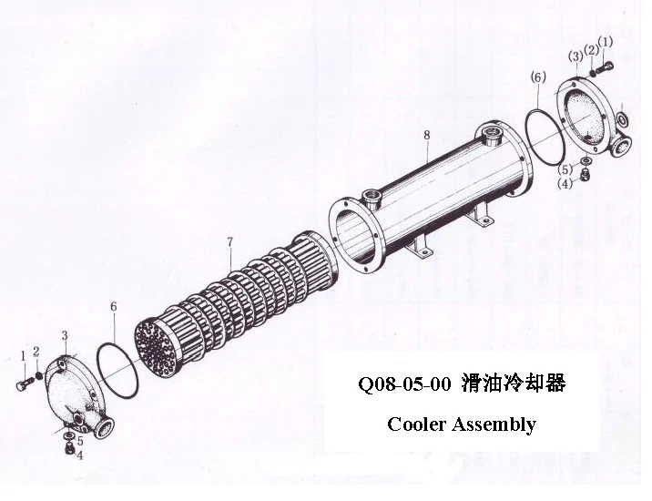
No. | Part No. | Part Name | Qty. | Remarks |
| 1 | GB/T5783 – 2000 M8×25 | Bolt | 8 | / |
| 2 | GB/T93 – 1987 8 | Washer | 8 | / |
| 3 | Q08 – 05 – 01A | End cover | 2 | / |
| 4 | GB/T5786 – 2000 M10×1×20 | Bolt | 1 | / |
| 5 | GB/T848 – 2002 10 | Washer | 1 | / |
| 6 | GB/T3452.1 – 2005 100×5.3 | “O” ring | 1 | / |
| 7 | Q08 – 05 – 100 | Cooler tube assembly | 1 | / |
| 8 | Q08 – 05 – 200A | Cooler casing | 1 | / |
| ——END—— | ||||
Note: All Above Data are Just for Reference, All Data Might Change Without Notices or Updates, Please Contact Our Sales Team to Confirm All Details Via WhatsApp or Email.

Engine Sale Manual

Installation Drawing

Installation Manual

Operation Manual

Parts Catalogue

Report & Certifcate
Tags: