The speed input range of the Advance GWS60.66 marine gearbox is 400-1900 RPM, with engine input power from 253.6 kW to 3648 kW. the reduction ratio range is 1.97-5.97 the transmission capacity range is 0.634-1.92 kW/RPM, the rated propeller thrust is 140 KN, and the input shaft is in the train Opposite to the output shaft.Advance GWC36.39 marine gearbox is composed of transmission shaft, output coupling, input coupling, oil pressure gauge, oil Filter, control system, oil pump and other important components.Advance GWC36.39 marine gearboxes provides two types of control system which are electric control and pneumatic control for customers to choose. To meet the different requirement of coupling with different engine brand and models, Advance GWC36.39 marine gearboxes available in engine flywheel sizes.All of our Advance GWC series marine gearbox can provide CCS classification certificate, some of series can provide international classifications with extra costs which mainly including French BV, British LR, American ABS, Japanese NK , Norway DNV-GL, Russia RS, South Korea KR, Italy RINA and other classification societies.
Advantages Of Advance GWS60.66 Marine Gearbox Parts
-
Gearbox novel structure, so that its use becomes very reliable. The excellent design makes the gearbox and engine arrangement more soft and smooth.
-
It can be matched with high-speed diesel engines at home and abroad, and can be arranged in vertical, horizontal and inclination according to the needs of users.
-
The gearbox have adapted to combined design, and all running parts have been carefully designed and machined to the highest standards for less wasted fuel, smooth operation which can be fitted to most engine models.
-
2-stage deceleration, the input and output are at the same center, and when the running direction is the same, it has the function of reverse clutch deceleration.
-
Professional gearbox specialists and after-sales service, spare parts directly available from stock.
Technical Specifications
| Gearbox Model: | GWS60.66 |
| Input Speed: | 400-1200 r / min |
| Power: | N/A |
| Center Distance: | N/A |
| Trans.Capacity: | 5.05 kw/r/min |
| Reduction Ratio: | 2.00-3.95 |
| Rated Thrust: | 450 kN |
| Dimension: | N/A |
| Net Weight: | 15000 kg |
| Lead Time: | 15-30 Working Days |
| Payment Terms: | T/T ,L/C |

Click Kit Name to Check Part List
- Inlet group GWS60.66 - 02 - 100 1
- Output Assembly
- Housing Assembly
- Pump Transmission Assembly
- Piping Assembly
No. |
Description |
Parts No. |
Qty |
Remarks |
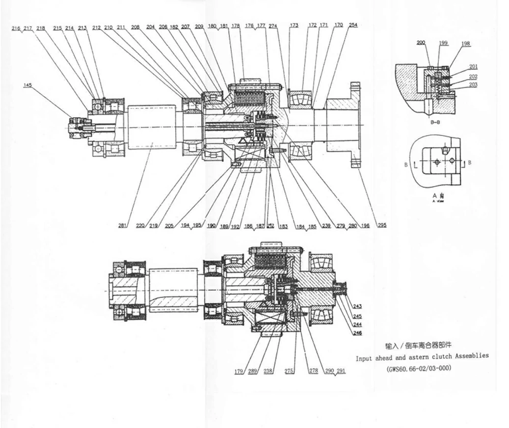
| 145 | Inlet group | GWS60.66 – 02 – 100 | 1 | \ |
| 170 | Sprag for shaft | GWC60.66 – 01 – 003 | 1 | \ |
| 171 | Clutch front spacer | 4/0400/5298/0 | 2 | GWC60.66 – 270 |
| 172 | Bearing 22344CC/W33 | 22344CC/W33 | 2 | 220×460×145 |
| 173 | Adjusting ring | 4/0402/0201/0 | 2 | GWC60.66 – 173 |
| 176 | Stud | GWS60.66 – 02 – 176 | 32 | \ |
| 177 | Nut | GWC60.66 – 02 – 177 | 64 | \ |
| 178 | Right – hand clutch casing gear | GWC60.66 – 02 – 004 | 1 | \ |
| 179 | Left – hand clutch casing gear | GWC60.66 – 03 – 001 | 1 | \ |
| 180 | In. frictional plate | 3/0539/0061/2 | 20 | \ |
| 181 | Ex. Frictional plate | 3/0530/0049/0 | 20 | \ |
| 182 | Disc carrier | GWL60.66 – 182 | 2 | \ |
| 183 | Clutch piston | GWL60.66 – 183 | 2 | \ |
| 184 | X – ring | 4432 | 2 | Φ149.9×135.9×7 |
| 185 | Sprag | S52029 – 432 | 2 | Φ137.2×6.4×1.25 |
| 186 | X – ring | 4462 | 2 | Φ431.96×417.96×7 |
| 187 | Sprag | \ | 2 | Φ417.2×6.4×1.25 |
| 189 | Spring | DIN2093 | 10 | C200 DIN2093 |
| 190 | Spring sleeve | GWL60.66 – 190 – 190 – 1 | 1 | \ |
| 192 | Plug | Q21 – 38 | 6 | \ |
| 194 | Baffle with hole | 4/0406/5131/0 | 2 | GWC60.66 – 194 |
| 195 | Screw M12×30 | GB70 – 85 | 12 | \ |
| 196 | Screw M12×65 | GB70 – 85 | 12 | \ |
| 198 | Drain valve body | 3/0931/0118/0 | 4 | GWC60.66 – 198 |
| 199 | Drain valve piston | 4/0903/0079/0 | 4 | GWC60.66 – 199 |
| 200 | Screw M6×40 | GB5783 – 86 | 8 | \ |
| 201 | Screw M6×8 | GB71 – 85 | 8 | \ |
| 202 | Screw M5×10 | GB71 – 85 | 4 | \ |
| 203 | Pressured spring | GB2089 – 94 | 1 | \ |
| 204 | Clutch casing flange | 2/0582/5039/0 | 2 | GWC60.66 – 204 |
| 205 | Pin | GB119 – 86 | 4 | \ |
| 206 | Bearing | GB/T285 – 94 | 2 | 300×460×118 |
| 207 | Spacer | GWC60.66 – 02 – 008 | 2 | \ |
| 208 | Clutch rear spacer | 4/0401/5098/0 | 2 | GWC60.66 – 208 |
| 209 | Key | GB1096 – 79 | 2 | \ |
| 210 | Bearing | GB/T283 – 94 | 4 | 180×380×126 |
| 211 | Circlip for shaft | GB894 – 86 | 2 | \ |
| 212 | Spacer | GWC60.66 – 02 – 007 | 2 | \ |
| 213 | Spacer | GWC60.66 – 02 – 001 | 2 | \ |
| 214 | Spacer | GWC60.66 – 02 – 002 | 2 | \ |
| 215 | Bearing | GB/T294 – 94 | 2 | 180×380×75 |
| 216 | Tab washer for round nut | GB858 – 88 | 2 | \ |
| 217 | Round nut | GB812 – 88 | 2 | \ |
| 218 | Pin | GWC52.59 – 218 | \ | \ |
| 219 | Gland for flange | 3/0409/5006/0 | 2 | GWC60.66 – 195 |
| 220 | Screw M8×20 | GB70 – 85 | 12 | \ |
| 238 | Guiding ring sleeve | GWL – 239 – 239 – 1 | 1 | Select |
| 239 | Guiding ring sleeve | GWL – 239 – 239 – 1 | 1 | Select |
| 243 | Inlet seat | GWC52.59 – 02 – 243 | 1 | \ |
| 244 | Oil – in sleeve | GWC52.59 – 05 – 143 | 1 | \ |
| 245 | Sealing ring | 300 – 01 – 016 | 2 | \ |
| 246 | Screw M10×25 | GB70 – 85 | 6 | \ |
| 254 | O – ring | GB3452.1 – 92 | 1 | \ |
| 274 | Input cylinder | GWS60.66 – 274 | 1 | \ |
| 275 | Astern cylinder | GWS60.66 – 275 | 1 | \ |
| 278 | Oil hole board | GWC60.66 – 02 – 011 | 1 | \ |
| 279 | Emergency screw | 4/0224/5086/0 | 8 | GWC60.66 – 174 |
| 280 | Safety wire | GB/T343 – 94 | Several | \ |
| 281 | Pinion shaft | GWS60.66 – 02 – 281 | 2 | \ |
| 289 | Seal | GWL60.66 – 02 – 005 | 2 | \ |
| 290 | O – ring | GB3452.1 – 92 | 1 | \ |
| 291 | Hexagon head bolt | GB5783 – 86 | 6 | \ |
| 292 | O – ring | GB3452.1 – 92 | 1 | \ |
| 295 | Input flange | GWS60.66 – 295 – 1 | 1 | \ |
| ——END—— | ||||
No. |
Description |
Parts No. |
Qty |
Remarks |
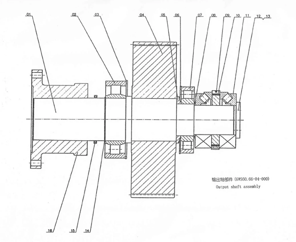
| 1 | Output shaft | GWS60.66 – 04 – 240 | 1 | \ |
| 2 | Bearing | NU2264 | 1 | 320×580×150 |
| 3 | Spacer | GWC60.66 – 04 – 002 | 1 | \ |
| 4 | Output gear | GWS60.66 – 04 – 284/71 | 1 | \ |
| 5 | Spacer ring | GWC60.66 – 04 – 011 | 1 | \ |
| 6 | Spacer | GWC60.66 – 04 – 007 | 1 | \ |
| 7 | Bearing | NU348 | 1 | 240×500×95 |
| 8 | Spacer | GWC60.66 – 04 – 004 | 1 | \ |
| 9 | Thrust ring | GWC60.66 – 04 – 005 | 1 | \ |
| 10 | Spring | GB2089 – 94 | 8 | \ |
| 11 | Bearing | 29444E | 2 | 220×420×122 |
| 12 | Gland | GWC60.66 – 04 – 006 | 1 | \ |
| 13 | Screw M24×65 | GB70 – 85 | 6 | \ |
| 14 | Circlip for shaft | GB/T894.1 – 86 | 1 | \ |
| 15 | O – ring | GB3452.1 – 92 | 1 | \ |
| 16 | Output flange | GWS60.66 – 04 – 001 | 1 | \ |
| ——END—— | ||||
No. |
Description |
Parts No. |
Qty |
Remarks |
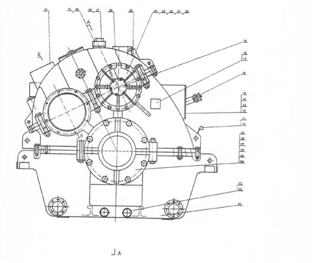
| 1 | Housing machining assemblies | GWS60.66 – 05 – 100 | 1 | \ |
| 2 | Plug screw M48×2 | Q20 – 01 | 3 | \ |
| 3 | Seal 48 | Q20 – 03A | 3 | \ |
| 4 | Sealing end – cover | GWC60.66 – 05 – 36 | 1 | \ |
| 5 | Bolt M20×80 | GB/T5782 – 86 | 2 | \ |
| 6 | Reamed bolt M16×80 | GB27 – 88 | 2 | \ |
| 7 | Bolt M20×50 | GB5783 – 86 | 16 | \ |
| 8 | Nut M16 | GB/T6170 – 86 | 6 | \ |
| 9 | Nut M20 | GB/T6170 – 86 | 2 | \ |
| 10 | Protective pipe | 4/0940/5157/0 | 1 | GWC60.66 – 54 |
| 11 | Dipstick | 4/8053/5193/0 | 1 | GWC60.66 – 53 |
| 12 | Inspection cover gasket | 3/0985/0036/0 | 3 | GWC60.66 – 65 – 75 |
| 13 | Inspection cover | 3/0454/0021/0 | 3 | GWC60.66 – 64 |
| 14 | Inspection window cover | GWS60.66 – 05 – 200 | 1 | \ |
| 15 | Hexagon head bolt M10×30 | GB/T5783 – 86 | 36 | \ |
| 16 | Oil filler group | GWC – 78 | 1 | \ |
| 17 | HC emblem mark 2 | Q25 – 13 | 1 | \ |
| 18 | Rivet 3×8 | GB827 – 86 | 8 | \ |
| 19 | Small end cover | GWS60.66 – 05 – 001 | 1 | \ |
| 20 | Input rear end cover | GWS60.66 – 05 – 32 | 1 | \ |
| 21 | Hexagon head bolt M16×40 | GB5783 – 86 | 8 | \ |
| 22 | Pin 12×30 | GB879 – 86 | 2 | \ |
| 23 | Hexagon head bolt M12×45 | GB5782 – 86 | 10 | \ |
| 24 | Nut M12 | GB6170 – 86 | 10 | \ |
| 25 | Narre plate | Q25 – 01 – 04A | 1 | \ |
| 26 | Hexagon head bolt M16×45 | GB5783 – 86 | 6 | \ |
| 27 | Electrical magnetic slip valve plate | GWC – 157.3 – 1 | 1 | \ |
| 28 | Screw M10×25 | GB70 – 85 | 4 | General parts (for electrical control) |
| 29 | Connection plate | 2/0930/0644/0 | 1 | GWC – 155 |
| 30 | Screw M10×55 | GB70 – 85 | 4 | \ |
| 31 | Hexagon head bolt M16×35 | GB5783 – 86 | 4 | \ |
| 32 | Split sealing cover | GWS60.66 – 05 – 26 | 1 | \ |
| 33 | Packing 15×15×730 | 1 | \ | |
| 34 | Reamed bolt M16×55 | GB27 – 88 | 2 | \ |
| 35 | Hexagon head bolt M20×70 | GB5782 – 86 | 8 | \ |
| 36 | Hexagon head bolt M16×55 | GB5783 – 86 | 2 | \ |
| 37 | Steering plate | Q25 – 06 | 1 | \ |
| 38 | Rivet 2×5 | GB827 – 86 | 2 | \ |
| 39 | Exhauster | Q29 – 06 | 1 | \ |
| 40 | Seal 30 | Q20 – 03A | 1 | \ |
| 41 | Plug screw M14×1.5 | JB1000 – 77 | 1 | \ |
| 42 | Packing 15×15×1060 | \ | \ | |
| 43 | Oil tray element | 3/0941/5053/0 | 1 | GWC60.66 – 48 |
| 44 | Hexagon bolt with wire holes on head M12×25 | GB32.1 – 88 | 4 | \ |
| 45 | Wire fuse φ1.6 | GB/T343 – 94 | Several | \ |
| 46 | Cover plate | GWC60.66 – 05 – 143 | 1 | \ |
| 47 | Hexagon head bolt M8×30 | GB5783 – 86 | 6 | \ |
| 48 | Inlet end cover | GWC60.66 – 05 – 141 | 1 | \ |
| 49 | Hexagon head bolt M20×65 | GB5782 – 86 | 8 | \ |
| 50 | Front end cover | GWS60.66 – 05 – 002 | 1 | \ |
| ——END—— | ||||
No. |
Description |
Parts No. |
Qty |
Remarks |
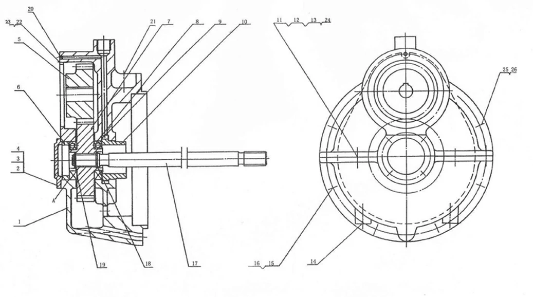
| 1 | Pump input casing | 1/0442/5063/0 | 1 | \ |
| 2 | End cover | 3/0438/0913/0 | 1 | \ |
| 3 | Bolt M10×30 | GB5783 – 86 | 4 | \ |
| 4 | Washer 10 | GB93 – 87 | 4 | \ |
| 5 | Spacer | 4/0401/5107/0 | 1 | \ |
| 6 | Pump gear | GWC60.66 – 06 – 001 | 1 | \ |
| 7 | Pump gear | GWC60.66 – 06 – 002 | 1 | \ |
| 8 | Bearing 6212 | GB/T276 – 94 | 2 | \ |
| 9 | Nilos ring | 4/0985/0687/0 | 1 | \ |
| 10 | Bushing | 4/0333/5020/0 | 1 | \ |
| 11 | Taper pin 10×30 | GB117 – 86 | 2 | \ |
| 12 | Hexagon head bolt M12×45 | GB5783 – 86 | 10 | \ |
| 13 | Washer 12 | GB93 – 87 | 10 | \ |
| 14 | Bolt M12×225 | GB5782 – 86 | 2 | \ |
| 15 | Bolt M16×50 | GB5783 – 86 | 8 | \ |
| 16 | Washer 16 | GB93 – 87 | 8 | \ |
| 17 | Pump transmission shaft | 3/0250/5017/0 | 1 | \ |
| 18 | Circlip 40 | GB894.1 – 86 | 1 | \ |
| 19 | Circlip 32 | GB894.1 – 86 | 1 | \ |
| 20 | Plug φ8 | Q21 – 13 | 1 | \ |
| 21 | Plug screw M14×1.5 | JB1000 – 77 | 1 | \ |
| 22 | Nut M16 | GB41 – 86 | 4 | \ |
| 23 | Double end stud M16×40 | GB898 – 88 | 4 | \ |
| 24 | Nut M12 | GB6170 – 86 | 12 | \ |
| 25 | Plug screw M33×2 | JB1000 – 77 | 1 | \ |
| 26 | Washer 33 | Q20 – 03 | 1 | \ |
| ——END—— | ||||
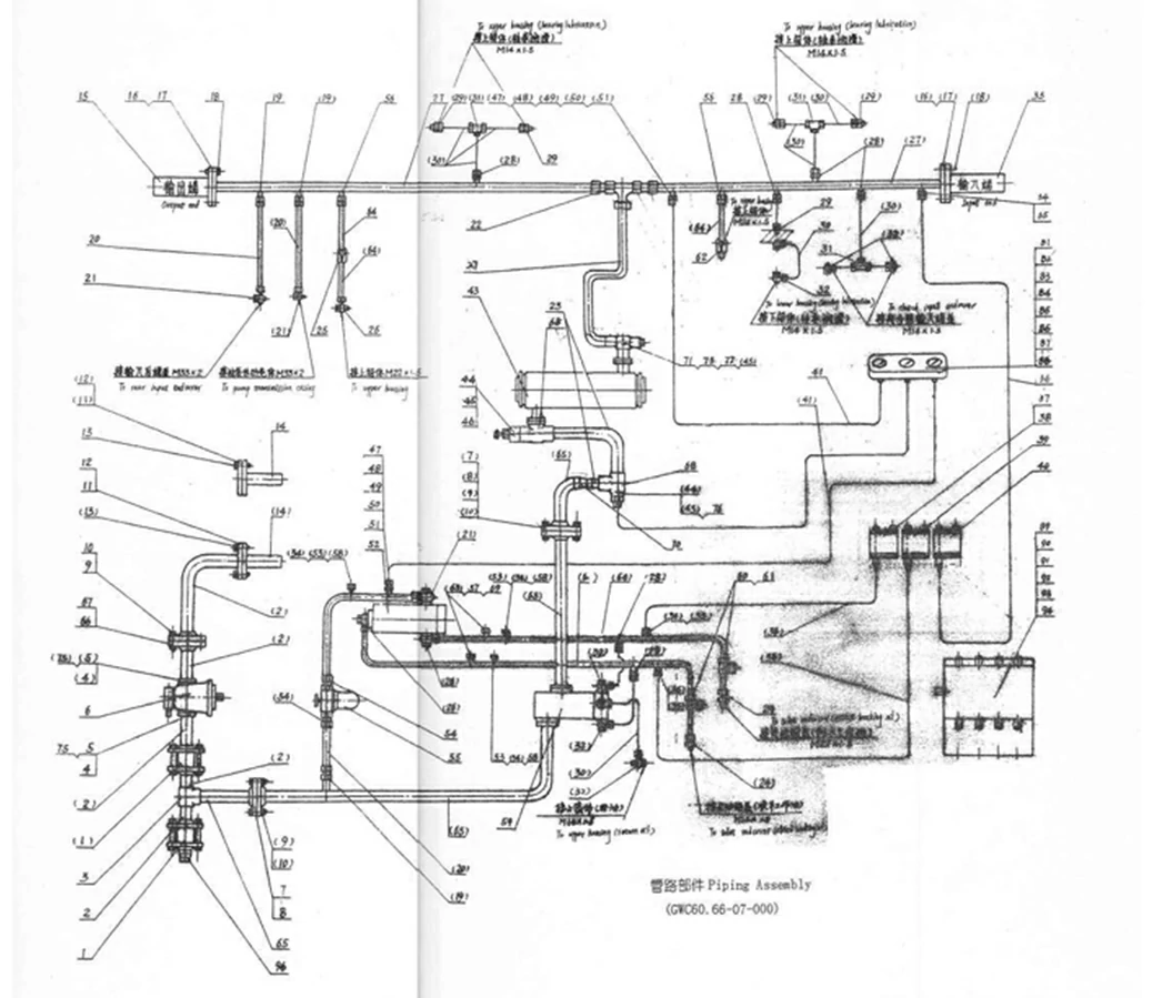
No. |
Description |
Parts No. |
Qty |
Remarks |
| 1 | Check valve subassembly | RK46 – NW80 – 00 | 2 | Series part |
| 2 | Steel tube 89×3.5 | GB/T8162 – 99 | 5 | \ |
| 3 | T – joint | GWC49.54 – 07 – 03 | 1 | \ |
| 4 | Pump flange | GWC49.54 – 07 – 508 | 2 | \ |
| 5 | Bolt M12×40 | GB5782 – 86 | 8 | \ |
| 6 | Oil pump KFS/250H₂OBNOO DH1+DKE5A25 | 1 | \ | \ |
| 7 | Flange C65×76 | DIN2633 | 4 | GWC49.54 – 507 |
| 8 | Sealing plate | GWC49.54 – 07 – 8 | 2 | \ |
| 9 | Bolt M16×60 | GB5782 – 86 | 20 | \ |
| 10 | Nut M16 | Gb6170 – 86 | 20 | \ |
| 11 | Flange | B80 ND6 DIN2527 | 2 | Series part 504.505, each one piece |
| 12 | Sealing plate | GWC49.54 – 07 – 12 | 4 | \ |
| 13 | Bolt M16×60 | GB5782 – 86 | 8 | \ |
| 14 | Suction pipe subassembly | GWC60.66 – 07 – 520 | 2 | \ |
| 15 | Nozzle tube element (output end) | GWC60.66 – 07 – 519 | 1 | \ |
| 16 | Flange | GWC60.66 – 07 – 510 | 2 | GWC – 510 |
| 17 | Sealing plate | GWC49.54 – 07 – 17 | 4 | No drawing |
| 18 | Bolt M10×45 | GB5782 – 86 | 8 | \ |
| 19 | Welding union joint Z28 | GB3747.1 – 83 | 3 | \ |
| 20 | Steel tube 28×2 | GB/T8162 – 88 | 4 | \ |
| 21 | Hinge union joint Z28 | GB3750.1 – 83 | 3 | \ |
| 22 | T – joint Z42 | GB3745.1 – 83 | 1 | \ |
| 23 | Steel tube 60×3.5 | GB/T8162 – 99 | 3 | \ |
| 24 | End – through union joint Z18 | GB3733.1 – 85 | 3 | \ |
| 25 | Backpressure valve | RHD18 | 1 | General part 541 |
| 26 | Hinge union joint Z18 | GB3750.1 – 83 | 3 | \ |
| 27 | Steel tube 42×2 | GB/T8162 – 99 | 3 | \ |
| 28 | Welding union joint Z10 | GB3747.1 – 83 | 6 | \ |
| 29 | End – through union joint Z10 | GB3733.1 – 85 | 5 | \ |
| 30 | Steel tube 10×1.5 | GB/T8162 – 99 | 14 | \ |
| 31 | T – joint Z10 | GB3745.1 – 83 | 3 | \ |
| 32 | Hinge union joint Z10 | GB3750.1 – 83 | 8 | \ |
| 33 | Nozzle tube element (input end) | GWC60.66 – 07 – 518 | 1 | \ |
| 34 | Connector M10×1 | GWC – 574 | 6 | General part 574 |
| 35 | End – through union joint Z6 | GB3733.1 – 85 | 3 | \ |
| 36 | Steel tube 6×1 | GB/T8162 – 99 | 3 | \ |
| 37 | Screw M4×25 | GB67 – 85 | 12 | \ |
| 38 | Pressure controller YWK – 50 – C | 1 | On order | \ |
| 39 | Pressure controller YWK – 50 – C | 1 | On order | \ |
| 40 | Pressure controller YWK – 50 – C | 1 | On order | \ |
| 41 | Steel tube 6×1 | GB1527 – 87 | 2 | \ |
| 42 | Filtering cooler LG12 | 1 | \ | \ |
| 43 | Connector M22×1.5 | GWC42.45 – 573 | 2 | Series part |
| 44 | Copper washer 22 | Q20 – 03 | 3 | \ |
| 45 | Temperature monitor 75°C JWGK – A | 1 | 0 – 100°C Selection | \ |
| 46 | Connector M14×1.5 | GWC – 576 | 2 | General part |
| 47 | Copper washer Ø12×0.3 | GWC – 579 | 2 | General part |
| 48 | Oil pipe joint | Q21 – 05 | 2 | CT007 – 73 |
| 49 | Oil pipe sleeve | Q21 – 06 | 2 | CT008 – 73 |
| 50 | Collar nut | Q21 – 07 | 2 | CT009 – 73 |
| 51 | Hydraulic control valve WL4A16B/1 | 1 | \ | \ |
| 52 | Copper washer 10 | Q20 – 03 | 3 | \ |
| 53 | End – through union joint Z28 | GB3733.1 – 85 | 2 | \ |
| 54 | Filter Γ41 – 43 | 1 | \ | \ |
| 55 | Welding union joint Z18 | GB3747.1 – 83 | 2 | \ |
| 56 | Copper washer 14 | Q20 – 03 | 3 | \ |
| 57 | Plug screw M10×1 | Q20 – 01 | 3 | \ |
| 58 | Two – step control valve | GWS45.49 – 152 – 000 | 1 | \ |
| 59 | Bayonet – type T – joint Z18 | GWC – 558 | 2 | General part 558 |
| 60 | Plug | GWC – 559 | 2 | General part 559 |
| 61 | Backpressure valve RHZ18 | 1 | General part 544 | \ |
| 62 | Connector | GWC49.54 – 07 – 63 | 3 | \ |
| 63 | Steel tube 18×1.5 | GB/T8162 – 99 | 5 | \ |
| 64 | Steel tube 76×3.5 | GB/T8162 – 99 | 4 | \ |
| 65 | Flange C80×89 DIN2633 | GWC49.54 – 506 | 4 | Series part |
| 66 | Sealing plate | GWC49.54 – 07 – 67 | 1 | No drawing |
| 67 | T – adapter | GWC49.54 – 07 – 68 | 1 | \ |
| 68 | Hexagon screw plug | GWC49.54 – 07 – 69 | 3 | Acc. To Q20 – 01 style |
| 69 | Reducer union | GWC49.54 – 07 – 70 | 1 | \ |
| 70 | Connector | GWC32.35 – 573 | 1 | \ |
| 71 | Plug screw M22×1.5 | Q21 – 15 | 1 | Use drain plug |
| 72 | Sealing plate | GWC49.54 – 07 – 75 | 2 | No drawing |
| 73 | Oil temperature joint | Q21 – 08 | 1 | \ |
| 74 | T – joint | GWC32.35 – 536 | 1 | \ |
| 75 | Dash board | Q25 – 05 | 1 | \ |
| 76 | Screw M4×8 | GB67 – 85 | 4 | \ |
| 77 | Nut M4 | GB6170 – 86 | 4 | \ |
| 78 | Washer 4 | GB97 – 85 | 4 | \ |
| 79 | Rubber vibration damper | Q19 – 01 – 00 | 4 | \ |
| 80 | Pressure gauge YN60ZT | 1 | 0 – 4Mpa | \ |
| 81 | Oil temperature indicator WT102 | 1 | 0 – 105°C | \ |
| 82 | Pressure gauge YT102 | 1 | 0 – 0.6Mpa | \ |
| 83 | Installation plate | GWC49.54 – 07 – 89 | 1 | \ |
| 84 | Bolt M8×16 | GB5783 – 86 | 8 | \ |
| 85 | Water proof terminal box | JXT18 – 14 | 1 | \ |
| 86 | Washer 8 | GB93 – 87 | 8 | \ |
| 87 | Nut M8 | GB6170 – 86 | 4 | \ |
| 88 | Marine cable CEF90/DA1.0mm² | 10m | \ | \ |
| 89 | Installation plate | GWC49.54 – 07 – 89 | 1 | \ |
| 90 | Bolt M8×16 | GB5783 – 86 | 8 | \ |
| 91 | Water proof terminal box | JXT18 – 14 | 1 | \ |
| 92 | Washer 8 | GB93 – 87 | 8 | \ |
| 93 | Nut M8 | GB6170 – 86 | 4 | \ |
| 94 | Marine cable | CEF90/DA1.0mm² | 10m | \ |
| ——END—— | ||||
Note: All Above Data are Just for Reference, All Data Might Change Without Notices or Updates, Please Contact Our Sales Team to Confirm All Details Via WhatsApp or Email.

Engine Sale Manual

Installation Drawing

Installation Manual

Operation Manual

Parts Catalogue