The speed input range of the Advance HCT1100 marine gearbox is 600-1900 RPM, with engine input power from 1240.7 kW to 1607.4 kW. the center distance is 500 mm, the reduction ratio range is 4.94-8.9, the transmission capacity range is 0.653-0.846 kW/RPM, the rated propeller thrust is 150 KN, and the input shaft is in the train Opposite to the output shaft.
Advance HCT1100 marine gearbox is composed of transmission shaft, output coupling, input coupling, oil pressure gauge, oil Filter, control system, oil pump and other important components.
Advance HCT1100 marine gearboxes provides three types of control system which are push-pull flexible shaft, electric control and pneumatic control for customers to choose. To meet the different requirement of coupling with different engine brand and models, Advance HCT1100 marine gearboxes available in engine flywheel sizes ……
All of our Advance 1100 series marine gearbox can provide CCS classification certificate, some of series can provide international classifications with extra costs which mainly including French BV, British LR, American ABS, Japanese NK , Norway DNV-GL, Russia RS, South Korea KR, Italy RINA and other classification societies.
Advantages Of Advance HCT1100 Marine Gearbox Parts
-
Advanced design and sophisticated manufacturing to adapt to various harsh working conditions! High-strength parts, strong ability to work under heavy loads.
-
Cylinder block and cylinder head adopt integrated design. The occurrence of engine water leakage and oil leakage is prevented, and the parts are about 40% less than other similar engines. The failure rate is greatly reduced.
-
Using forged steel camshaft and crankshaft, high-strength cylinder block design, multiple parts cast on the cylinder block, high rigidity, high pressure resistance, good reliability, and longer service life.
-
The cylinder bore adopts a platform mesh honing design. The perfect geometric structure effectively prevents oil leakage, and the use of advanced technology such as new piston ring components and gasket crimping and molding reduces oil loss.
-
The five key systems of the electronically controlled engine are all developed by DCEC, and have been applied and verified in different fields around the world to ensure the excellent economy and reliability of the product.
-
By optimizing the control strategy and combining with the actual operating conditions of the equipment, the fuel economy can be further improved.
Technical Specifications
| Gearbox Model: | HCT1100 |
| Input Speed: | 600-1900 RPM |
| Power: | 1240.7-1607.4 kW @ 1900 RPM |
| Center Distance: | 500 mm |
| Trans.Capacity: | 0.653-0.846kW / RPM |
| Reduction Ratio: | 4.94-8.9 |
| Rated Thrust: | 150 kN |
| Dimension: | 1150 mm * 1350 mm * 1547 mm |
| Net Weight: | 3200 kg |
| Lead Time: | 15-30 Working Days |
| Payment Terms: | T/T ,L/C |

Search by Part No. or Part Name
Click Kit Name to Check Part List
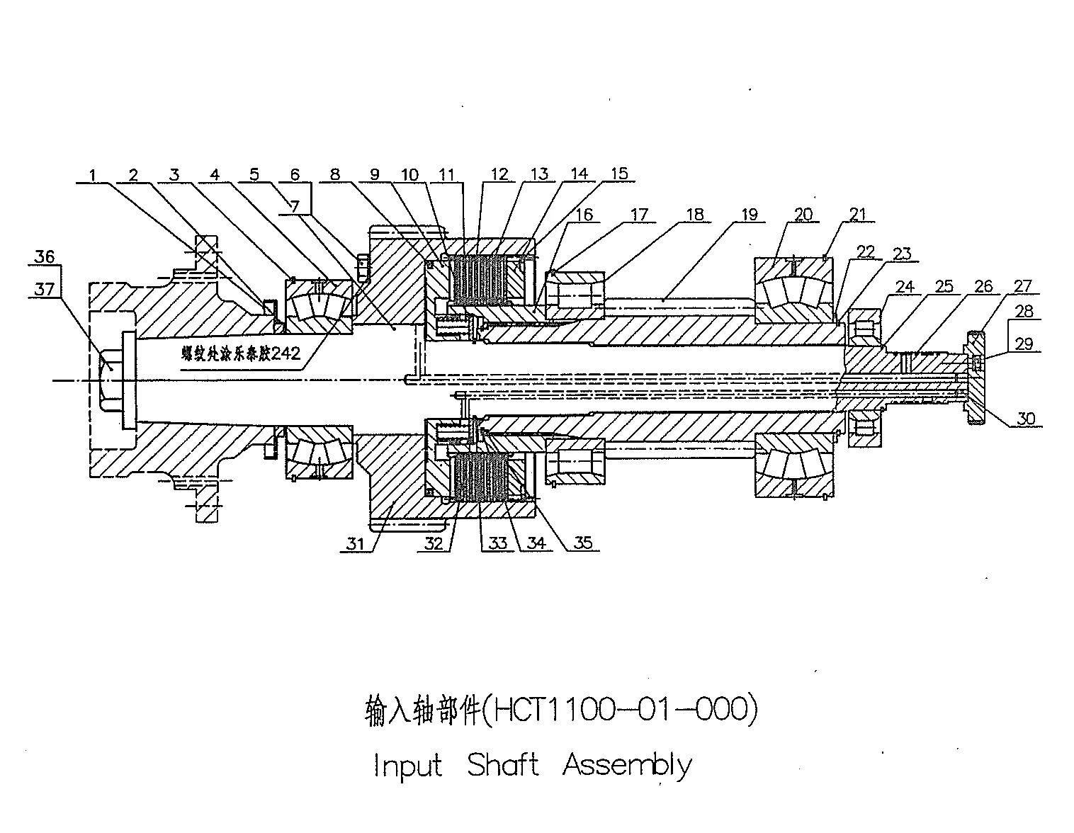
- Input Shaft Assembly
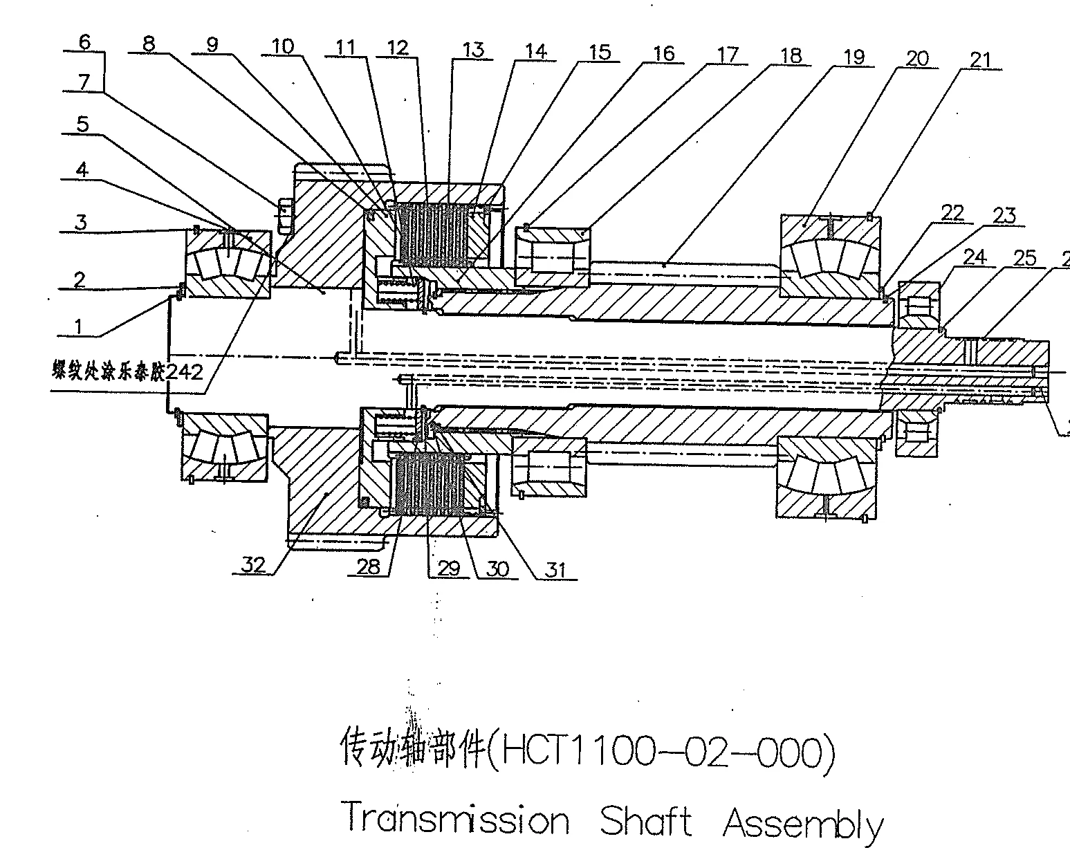
- Transmission Shaft Assembly
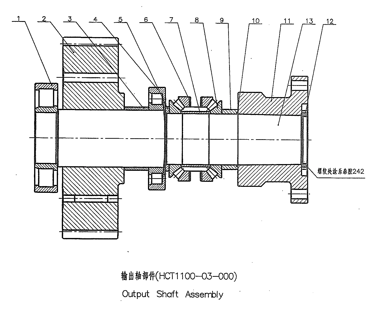
- Output Shaft Assembly
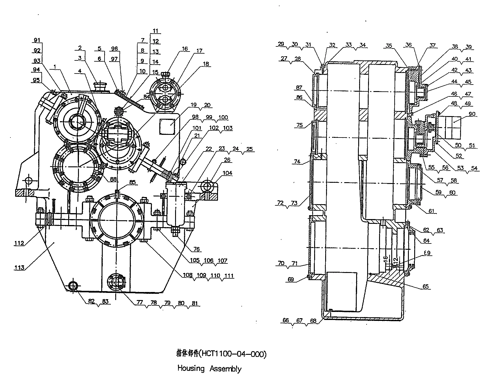
- Housing Assembly
- Counter Shaft Assembly
- Distributor Assembly
No. |
Part Name |
Part No. |
Qty. |
Remarks |
| 1 | Fastening bolt | 135—01—003 | 1 | / |
| 2 | Pin | B12×30GB120—76 | 2 | / |
| 3 | Input Coupling adaptor | 135—01—031 | 1 | / |
| 4 | Thrust plate | 135—01—030 | 1 | / |
| 5 | Adjusting plug | 135—01—002 | 1 | / |
| 6 | Washer | 135—01—029 | 1 | / |
| 7 | Snap ring | 85GB894—76 | 1 | / |
| 8 | Splashing pan | 135—01—028 | 1 | / |
| 9 | Stop ring | 180GB305—64 | 1 | / |
| 10 | Bearing | 50317 | 1 | / |
| 11 | Spraying washer | 135—01—027 | 1 | / |
| 12 | Bolt | M10×25GB32—76 | 6 | / |
| 13 | Input shaft sleeve | 135—01—004 | 1 | / |
| 14 | Left-hand gear | 135—01—005 | 1 | / |
| 15 | Bearing | 42313 | 2 | / |
| 16 | Bearing spacer | 135—01—006 | 1 | / |
| 17 | Thrust ring at input end | 135—01—007 | 1 | / |
| 18 | Snap ring | 135—01—008 | 2 | / |
| 19 | Drive gear | 135-01-009/6(ratio: 6:1) | 1 | Mn = 4, Z = 16 |
| 19 | Drive gear | 135-01-009/5.5(ratio: 5.5:1) | 1 | Mn = 4.5, Z = 15 |
| 19 | Drive gear | 135-01-009/5(ratio: 5:1) | 1 | Mn = 4.5, Z = 16 |
| 19 | Drive gear | 135-01-009/4.5(ratio: 4.5:1) | 1 | Mn = 4.5, Z = 17 |
| 19 | Drive gear | 135-01-009/4(ratio: 4:1) | 1 | Mn = 4.5, Z = 19 |
| 19 | Drive gear | 135-01-009/3.5(ratio: 3.5:1) | 1 | Mn = 4.5, Z = 21 |
| 19 | Drive gear | 135-01-009/3(ratio: 3:1) | 1 | Mn = 4.5, Z = 24 |
| 19 | Drive gear | 135-01-009/2.5(ratio: 2.5:1) | 1 | Mn = 4.5, Z = 27 |
| 19 | Drive gear | 135-01-009/2(ratio: 2:1) | 1 | Mn = 4.5, Z = 32 |
| 20 | Bearing | 2613K (2613K-1 for 2:1) | 1 | / |
| 21 | Clutch casing | 135—01—024A | 1 | / |
| 22 | Socket head cap screw | 135—01—032 | 4 | / |
| 23 | Supporting ring of torsional shaft | 135—01—012 | 1 | / |
| 24 | Carrier of frictional plates | 135—01—011A | 1 | / |
| 25 | Outer friction plate single sintered | 1201—0018A | 2 | / |
| 26 | Inner Friction plate | 1201—0019 | 5 | / |
| 27 | Outer friction plate | 1201—0007A | 4 | / |
| 28 | Torsional shaft | 135—01—010 | 1 | / |
| 29 | Spring cup | 135—01—025 | 1 | / |
| 30 | Spring | 135—01—018 | 6 | / |
| 31 | Piston | 135—01—014 | 1 | / |
| 32 | Snap ring | 20GB895—76 | 1 | / |
| 33 | Oil distributor | 135—01—019 | 1 | / |
| 34 | Distributor sleeve | 135—01—020A | 1 | / |
| 35 | Locking bar | 135—01—026 | 1 | / |
| 36 | Sleeve ring | 135—01—021 | 1 | / |
| 37 | Snap ring | 40GB894—76 | 1 | / |
| 38 | Spring washer | 8GB93—76 | 1 | / |
| 39 | Bolt | M8×16GB21—76 | 1 | / |
| 40 | Emergency screw | 135—01—013 | 3 | / |
| 41 | Copper washer | 12Q20—03 | 3 | / |
| 42 | Oil sealing | 135—01—015A | 1 | / |
| 43 | Thrust plate | 135—01—016 | 1 | / |
| 44 | Snap ring | 135—01—023 | 1 | / |
| 45 | Key | 135—01—017 | 1 | / |
| 46 | Screw | M8×18GB65—76 | 3 | / |
| 47 | Cylindrical pin | 12gu×20GB119—76 | 3 | / |
| 48 | Washer 6 | GB93—76 | 1 | / |
| ——END—— | ||||
No. |
Part Name |
Part No. |
Qty. |
Remarks |
| 1 | Fastening bolt | 135—02—001 | 1 | / |
| 2 | Snap ring | 75GB894—76 | 1 | / |
| 3 | Stop ring | 160GB305—64 | 1 | / |
| 4 | Bearing | 50315 | 1 | / |
| 5 | Thrust plate | 135—01—030 | 1 | / |
| 6 | Adjusting plug | 135—01—002 | 1 | / |
| 7 | Shaft sleeve | 135—02—002 | 1 | / |
| 8 | Right-hand gear | 135—02—003 | 1 | / |
| 9 | Bearing | 42313 | 2 | / |
| 10 | Thrust ring | 135—01—007 | 1 | / |
| 11 | Bearing spacer | 135—01—006 | 1 | / |
| 12 | Ring | 135—01—008 | 2 | / |
| 13 | Drive gear | 135-01-009/6 | 1 | / |
| 13 | Drive gear | 135-01-009/5.5 | 1 | / |
| 13 | Drive gear | 135-01-009/5 | 1 | / |
| 13 | Drive gear | 135-01-009/4.5 | 1 | / |
| 13 | Drive gear | 135-01-009/4 | 1 | / |
| 13 | Drive gear | 135-01-009/3.5 | 1 | / |
| 13 | Drive gear | 135-01-009/3 | 1 | / |
| 13 | Drive gear | 135-01-009/2.5 | 1 | / |
| 13 | Drive gear | 135-01-009/2 | 1 | / |
| 14 | Bearing | 2613K (2613K-1for2:1) | 1 | / |
| 15 | Clutch casing | 135—01—024A | 1 | / |
| 16 | Supporting ring | 135—01—012 | 1 | / |
| 17 | Carrier of frictional plates | 135—01—011A | 1 | / |
| 18 | Outer friction plate single sintered | 1201—0018A | 2 | / |
| 19 | Inner Friction plate | 1201—0019 | 5 | / |
| 20 | Outer friction plate | 1201—0007A | 4 | / |
| 21 | Torsional shaft | 135—01—010 | 1 | / |
| 22 | Spring cup | 135—01—025 | 1 | / |
| 23 | Spring | 135—01—018 | 6 | / |
| 24 | Piston | 135—01—014 | 1 | / |
| 25 | Oil sealing | 135—01—015A | 1 | / |
| 26 | Socket head cap screw | 135—01—032 | 4 | / |
| 27 | Astern thrust plate | 135—02—004 | 1 | / |
| 28 | Screw | M8×18GB65—76 | 3 | / |
| 29 | Key | 135—01—017 | 1 | / |
| 30 | Elastic Snap ring | 135—01—023 | 1 | / |
| 31 | Snap ring | 20GB895—76 | 1 | / |
| 31 | Snap ring | 20GB895—76 | 1 | / |
| 32 | Oil distributor | 135—01—019 | 1 | / |
| 33 | Distributor sleeve | 135—01—020A | 1 | / |
| 34 | Sleeve ring | 135—01—021 | 1 | / |
| 35 | Snap ring | 40GB894—76 | 1 | / |
| 36 | Spring washer | 8GB93—76 | 1 | / |
| 37 | Bolt | M8×16GB21—76 | 1 | / |
| 38 | Cylindrical pin | 12ga×20GB119—76 | 3 | / |
| 39 | Washer | GB93—76 | 1 | / |
| 40 | Screw | M6×10GB66—76 | 1 | / |
| ——END—— | ||||
No. |
Part Name |
Parts No. |
Qty. |
Remarks |
| 1 | Bolt | M10×22GB21—76 | 2 | / |
| 2 | Washer | 10GB93—76 | 2 | / |
| 3 | Adjusting plug | 135—03—001 | 1 | / |
| 4 | Thrust bearing bush | 135—03—010 | 1 | / |
| 5 | Seal ring | 135—03—009 | 1 | / |
| 6 | “O” ring | 150×5.7GC1235—76 | 1 | / |
| 7 | Bearing | 9069414 | 1 | / |
| 8 | Bearing | 42316 | 1 | / |
| 9 | Spacer | 135—03—002 | 1 | / |
| 10 | Gear | 135-03-008/6 | 1 | / |
| 10 | Gear | 135-03-008/5.5 | 1 | / |
| 10 | Gear | 135-03-008/5 | 1 | / |
| 10 | Gear | 135-03-008/4.5 | 1 | / |
| 10 | Gear | 135-03-008/4 | 1 | / |
| 10 | Gear | 135-03-008/3.5 | 1 | / |
| 10 | Gear | 135-03-008/3 | 1 | / |
| 10 | Gear | 135-03-008/2.5 | 1 | / |
| 10 | Gear | 135-03-008/2 | 1 | / |
| 11 | Spacer | 135—03—003 | 1 | / |
| 12 | Bearing | 3520 | 1 | / |
| 13 | Pressure Spring | 1.2×12×13JB272—60 | 6 | / |
| 14 | Splashing pan | 135—03—004 | 1 | / |
| 15 | Thrust bearing seat | 135—03—005A | 1 | / |
| 16 | “O” ring | 180×5.7GB1235—76 | 1 | / |
| 17 | Output shaft | 135—03—007 | 1 | / |
| 18 | Nut | M16GB52—76 | 8 | / |
| 19 | Washer | 16GB93—76 | 8 | / |
| 20 | Companion coupling | 135—03—006B | 1 | / |
| 21 | Bolt | M16×75GB27—76 | 8 | / |
| 22 | Oiled asbestos packing | F8JB68—64 | 1 | / |
| 23 | Thrust plate | 135—03—011 | 1 | / |
| 24 | Washer | 8GB93—76 | 6 | / |
| 25 | Bolt | M8×25GB21—76 | 6 | / |
| ——END—— | ||||
No. |
Part Name |
Parts No. |
Qty. |
Remarks |
| 1 | Bolt | M10×35GB21—76 | 16 | / |
| 2 | Pin | 3jc4×20GB119—76 | 1 | / |
| 3 | Bolt | M10×105GB21—76 | 2 | / |
| 4 | Bolt | M10×35GB70—76 | 4 | / |
| 5 | Washer | 10GB93—76 | 37 | / |
| 6 | front end Cover | 135—04—003 | 1 | / |
| 7 | Bell housing | 135—04—001—1 ( SAEJ620cNold) | 1 | / |
| 7 | Bell housing | 135—04—001 ( 6135 diesel engine) | 1 | / |
| 8 | Cover | 1601—0018 | 1 | / |
| 9 | Washer | 6GB93—76 | 2 | / |
| 10 | Button head cap screw | M6×12GB67—76 | 2 | / |
| 11 | Dip stick knob | 135—04—601 | 1 | / |
| 12 | “O” ring | 16×2.4GB1235—76 | 1 | / |
| 13 | Oil dip stick | 135—04—602 | 1 | / |
| 14 | Bolt | M8×25GB21—76 | 8 | / |
| 15 | Washer | 8GB93—76 | 28 | / |
| 16 | Top Cover | 135—04—009 | 2 | / |
| 17 | Casket | 1204—0004 | 2 | / |
| 18 | Plug | Q21—13 | 4 | / |
| 19 | Copper washer | 14Q20—03 | 18 | / |
| 20 | Washer | 135—04—020 | 3 | / |
| 21 | Piping assembly, astern | 135—04—300B | 1 | / |
| 22 | Piping assembly, ahead | 135—04—400B | 2 | / |
| 23 | Lub. oil piping | 135—04—500B | 1 | / |
| 24 | Adaptor | 135—04—019 | 3 | / |
| 25 | Adaptor screw | 135—04—022 | 1 | / |
| 26 | Adaptor screw | Q21—19 | 3 | / |
| 27 | Bolt | M8×75GB21—76 | 12 | / |
| 28 | Socket head cap screw | M8×55GB70—76 | 1 | / |
| 29 | Rear cover | 135—04—010 | 1 | / |
| 30 | Gasket | 135—04—011 | 1 | / |
| 31 | Gasket | 135—04—013 | 1 | / |
| 32 | Bolt | M10×65GB21—76 | 15 | / |
| 33 | Front cover | 135—04—103 | 1 | / |
| 34 | Gasket | 135—04—012 | 1 | / |
| 35 | Taper pin | 12×45GB118—76 | 4 | / |
| 36 | Upper housing | 135—04—101 | 1 | / |
| 37 | Oil shroud | 135—04—005 | 1 | / |
| 38 | Suction pipe | 135—04—007 | 1 | / |
| 39 | Clamper | 135—04—008 | 1 | / |
| 40 | “O” ring | 30×3.1GB1235—76 | 1 | / |
| 41 | Lower housing | 135—04—102 | 1 | / |
| 42 | Washer | 18GB93—76 | 4 | / |
| 43 | Bolt | M18×90GB21—76 | 4 | / |
| 44 | Plug | Z3/4″Q20—02 | 1 | / |
| 45 | washer | 8GB848—76H62y | 4 | / |
| 46 | Washer | 12GB93—76 | 22 | / |
| 47 | Bolt | M12×40GB21—76 | 10 | / |
| 48 | pin | 8ga×16GB119—76 | 2 | / |
| 49 | Breather cap | Q29—06 | 1 | / |
| 50 | Oil retainer | Q29—05 | 1 | / |
| 51 | Ring | Q29—04 | 1 | / |
| 52 | Eye bolt | M16GB825—76 | 2 | / |
| 53 | Stop screw | 135—04—002 | 2 | / |
| 54 | Gasket | 135—04—706 | 1 | / |
| 55 | Strainer | 135—04—700 | 1 | / |
| 56 | Strainer flange | 135—04—705 | 1 | / |
| 57 | Bolt | M8×25GB21—76Cr13 | 4 | / |
| 58 | Support | 135—04—004 135—04—004x₁ (special orders) | 2 | / |
| 59 | pin | 12×25GB120—76 (used for Cancel 135—04—004x₁ Cancel) | 4 | / |
| 60 | Bolt | M12×35GB21—76 | 12 | / |
| 61 | Bolt | M8×16GB21—76 | 4 | / |
| 62 | Gasket | 135—04—016 | 1 | / |
| ——END—— | ||||
No. |
Part Name |
Part No. |
Qty. |
Remarks |
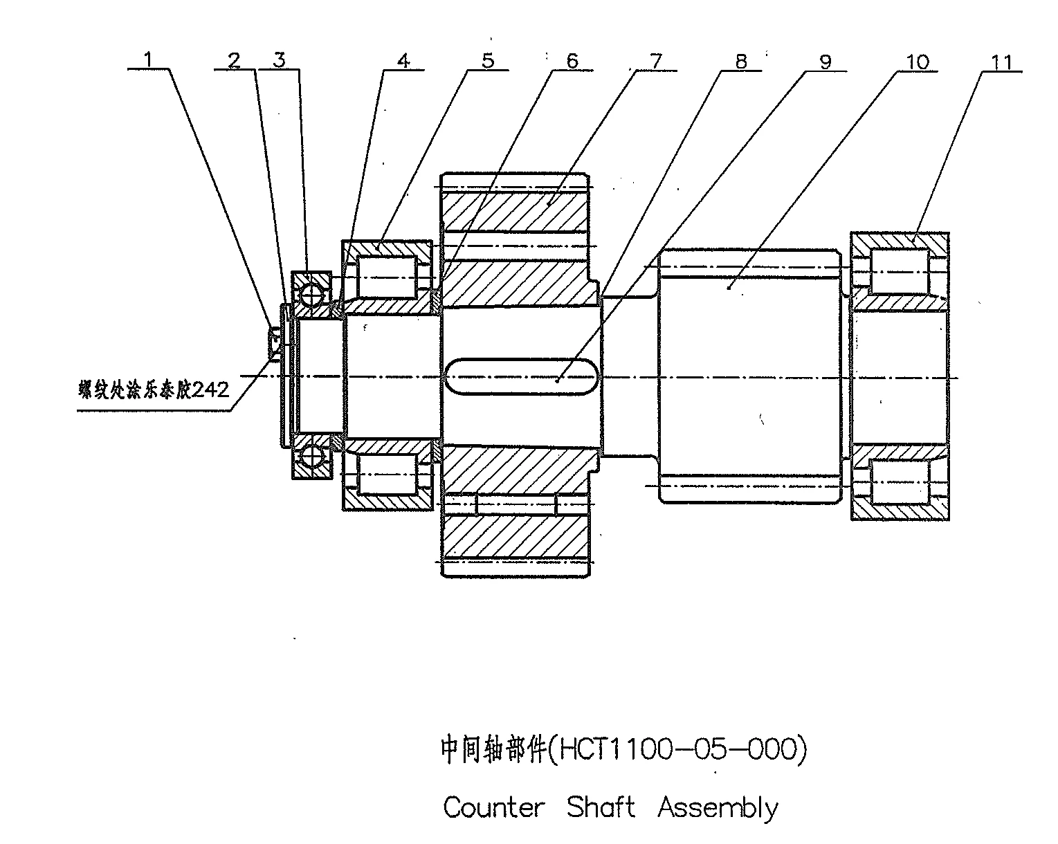
| 1 | Bolt M24x40 | GB/T5782 – 2000 | 3 | / |
| 2 | Plate | HCT1100 – 05 – 006 | 1 | / |
| 3 | Bearing 6224 | GB/T276 – 94 | 1 | / |
| 4 | Counter shaft spacer | HCT1100 – 05 – 005 | 1 | / |
| 5 | Bearing NJ2326 | GB/T283 – 94 | 1 | / |
| 6 | Counter Shaft space | HCT1100 – 05 – 004 | 1 | / |
| 7 | Counter shaft gear | HCT1100 – 05 – 002/53 | 1 | For i = 7.904 |
| 8 | Counter shaft gear | HCT1100 – 05 – 002/52 | 1 | For i = 7.346 |
| 9 | Counter shaft gear | HCT1100 – 05 – 002/51 | 1 | For i = 6.845 |
| 10 | Counter shaft gear | HCT1100 – 05 – 002/50 | 1 | For i = 6.391 |
| 11 | Counter shaft gear | HCT1100 – 05 – 002/49 | 1 | For i = 5.978 |
| 12 | Counter shaft gear | HCT1100 – 05 – 002/48 | 1 | For i = 5.602 |
| 13 | Counter Shaft space | HCT1100 – 05 – 003 | 1 | / |
| 14 | Bond 36×160 | GB/T1096 – 2003 | 1 | / |
| 15 | Counter shaft | HCT1100 – 05 – 001/19 | 1 | / |
| 16 | Bearing NJ2328 | GB/T283 – 94 | 1 | / |
| ——END—— | ||||
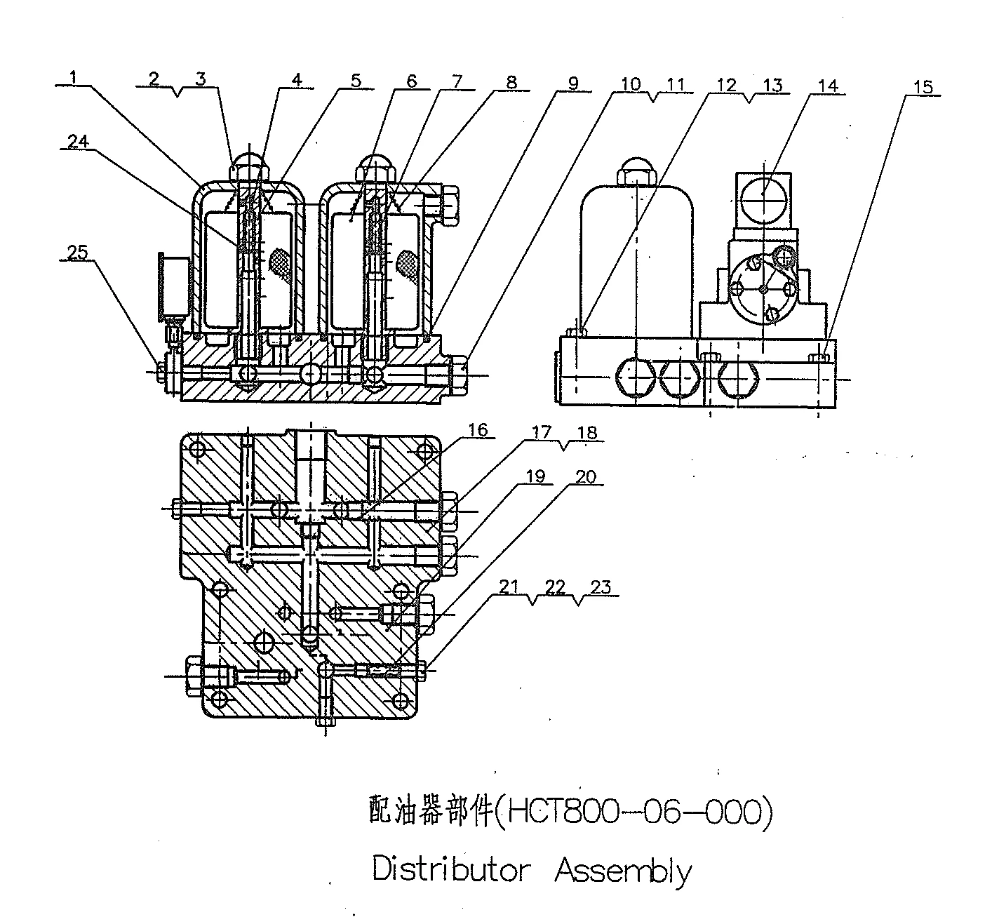
No. |
Part Name |
Part No. |
Qty. |
Remarks |
| 1 | Filter Case | HCT800 – 06 – 001 | 2 | / |
| 2 | Nut M20 | GB923 – 88 | 2 | / |
| 3 | Copper washer 20 | Q20 – 03 | 2 | / |
| 4 | Steel ball φ10 | GB308 – 89 | 2 | / |
| 5 | Stem | HCT800 – 06 – 002 | 2 | / |
| 6 | Coil – type filter HY36B – 5 | HY36B – 5 | 2 | / |
| 7 | Spring 0.8x9x35.8 HY36B – 5 | HY36B – 5 | 2 | / |
| 8 | Spring | HCT800 – 06 – 003 | 2 | / |
| 9 | “O” – ring 100×5.3 | GB3452.1 – 92 | 2 | / |
| 10 | Drain Plug M22x1.5 | Q21 – 15A | 4 | / |
| 11 | Copper washer 22 | Q20 – 03A | 7 | / |
| 12 | Bolt M14x90 | GB/T5782 – 2000 | 2 | / |
| 13 | Washer 14 | GB/T93 – 87 | 6 | / |
| 14 | Hydraulic control system | Q06 – 13X1/14X1 – 00 | 1 | Push – pull soft shaft/electric control |
| 15 | Bolt M14x70 | GB/T5782 – 2000 | 4 | / |
| 16 | Plug M18x1.5 | HCT800 – 06 – 004 | 1 | / |
| 17 | Oil distribution plate | HCT800 – 06 – 005 | 1 | / |
| 18 | Gasket | HCT800 – 06 – 006 | 1 | / |
| 19 | Lub. valve stem | 300 – 06A – 003 | 1 | / |
| 20 | Spring 1.2×10×35 | GB2089 – 80 | 1 | / |
| 21 | Bolt M14×1.5 | Q21 – 01 | 3 | / |
| 22 | Copper washer 14 | Q20 – 03A | 2 | / |
| 23 | Plug 12 | Q21 – 44 | 2 | / |
| 24 | Pin B2.5×20 | GB/T119 – 2000 | 2 | / |
| 25 | Plug | HCT800 – 06 – 007 | 1 | / |
| ——END—— | ||||
Note: All Above Data are Just for Reference, All Data Might Change Without Notices or Updates, Please Contact Our Sales Team to Confirm All Details Via WhatsApp or Email.

Engine Sale Manual

Installation Drawing

Installation Manual

Operation Manual

Parts Catalogue

Report & Certifcate
Tags: