The speed input range of the Advance HCD600A marine gearbox is 1000-2100 RPM, with engine input power from 903 kW to 1029 kW. the center distance is 415 mm, the reduction ratio range is 4.18-5.71, the transmission capacity range is 0.43-0.49 kW/RPM, the rated propeller thrust is 90 KN, and the input shaft is in the train Opposite to the output shaft.
Advance HCD600A marine gearbox is composed of transmission shaft, output coupling, input coupling, oil pressure gauge, oil Filter, control system, oil pump and other important components.
Advance HCD600A marine gearboxes provides three types of control system which are push-pull flexible shaft, electric control and pneumatic control for customers to choose. To meet the different requirement of coupling with different engine brand and models, Advance HCD600A marine gearboxes provide different SAE size coupling and housing including SAE 00 0 1 Without, flywheel SAE 21 18 16 14 is available……
All of our Advance 600 series marine gearbox can provide CCS classification certificate, some of series can provide international classifications with extra costs which mainly including French BV, British LR, American ABS, Japanese NK , Norway DNV-GL, Russia RS, South Korea KR, Italy RINA and other classification societies.
Advantages Of Advance HCD600A Marine Gearbox Parts
-
Advanced design and sophisticated manufacturing to adapt to various harsh working conditions! High-strength parts, strong ability to work under heavy loads.
-
Cylinder block and cylinder head adopt integrated design. The occurrence of engine water leakage and oil leakage is prevented, and the parts are about 40% less than other similar engines. The failure rate is greatly reduced.
-
Using forged steel camshaft and crankshaft, high-strength cylinder block design, multiple parts cast on the cylinder block, high rigidity, high pressure resistance, good reliability, and longer service life.
-
The cylinder bore adopts a platform mesh honing design. The perfect geometric structure effectively prevents oil leakage, and the use of advanced technology such as new piston ring components and gasket crimping and molding reduces oil loss.
-
The five key systems of the electronically controlled engine are all developed by DCEC, and have been applied and verified in different fields around the world to ensure the excellent economy and reliability of the product.
-
By optimizing the control strategy and combining with the actual operating conditions of the equipment, the fuel economy can be further improved.
Technical Specifications
| Gearbox Model: | HCD600A |
| Input Speed: | 1000-2100 r / min |
| Power: | 903-1029 kW@ 2100 RPM |
| Center Distance: | 415 mm |
| Trans.Capacity: | 0.43-0.49 kW / rpm |
| Reduction Ratio: | 4.18-5.71 |
| Rated Thrust: | 90 kN |
| Dimension: | 745 mm * 1214 mm * 1271 mm |
| Net Weight: | 1550 kg |
| Lead Time: | 15-30 Working Days |
| Payment Terms: | T/T ,L/C |

Search by Part No. or Part Name
Click Kit Name to Check Part List
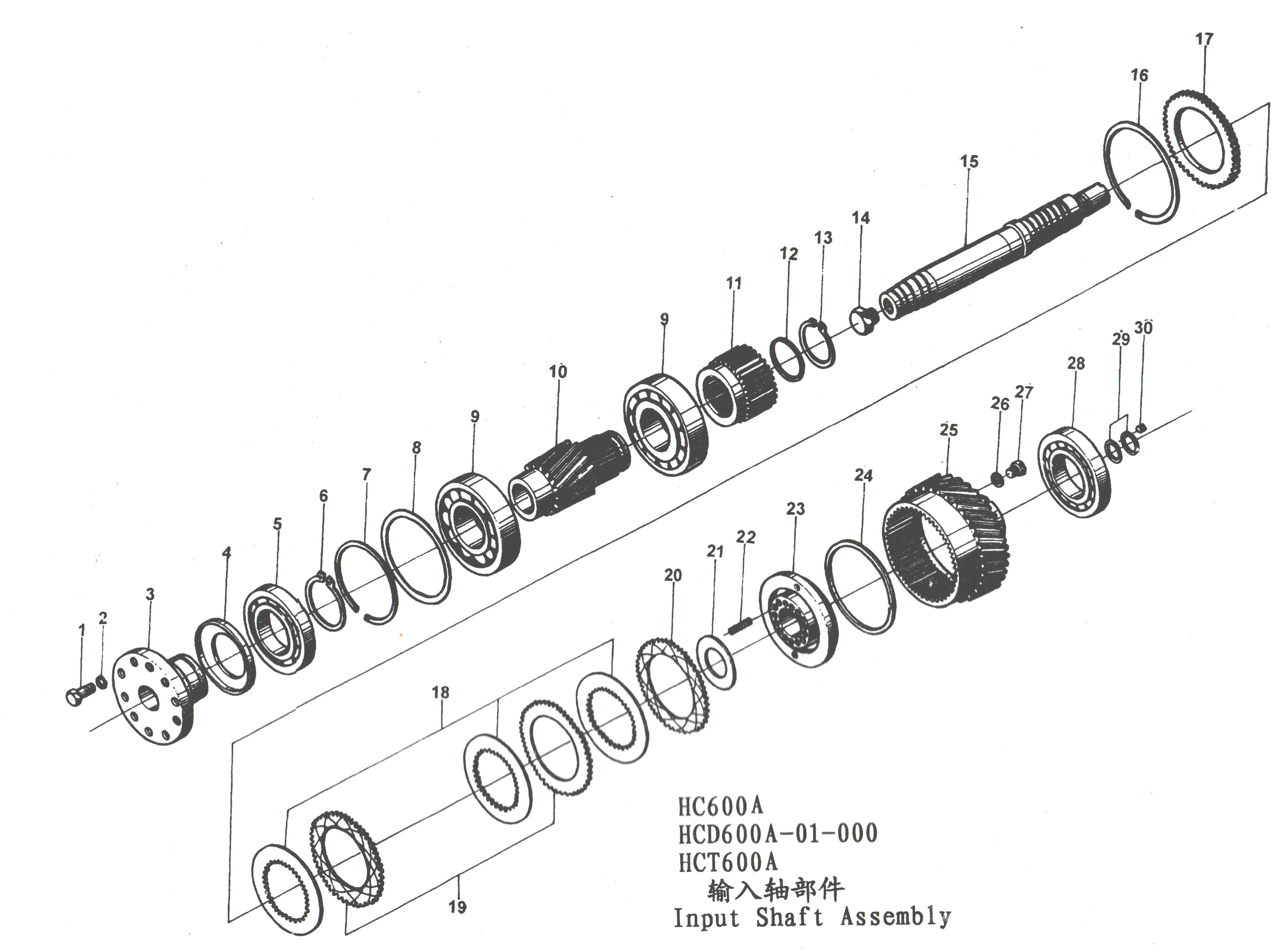
- Input Shaft Assembly
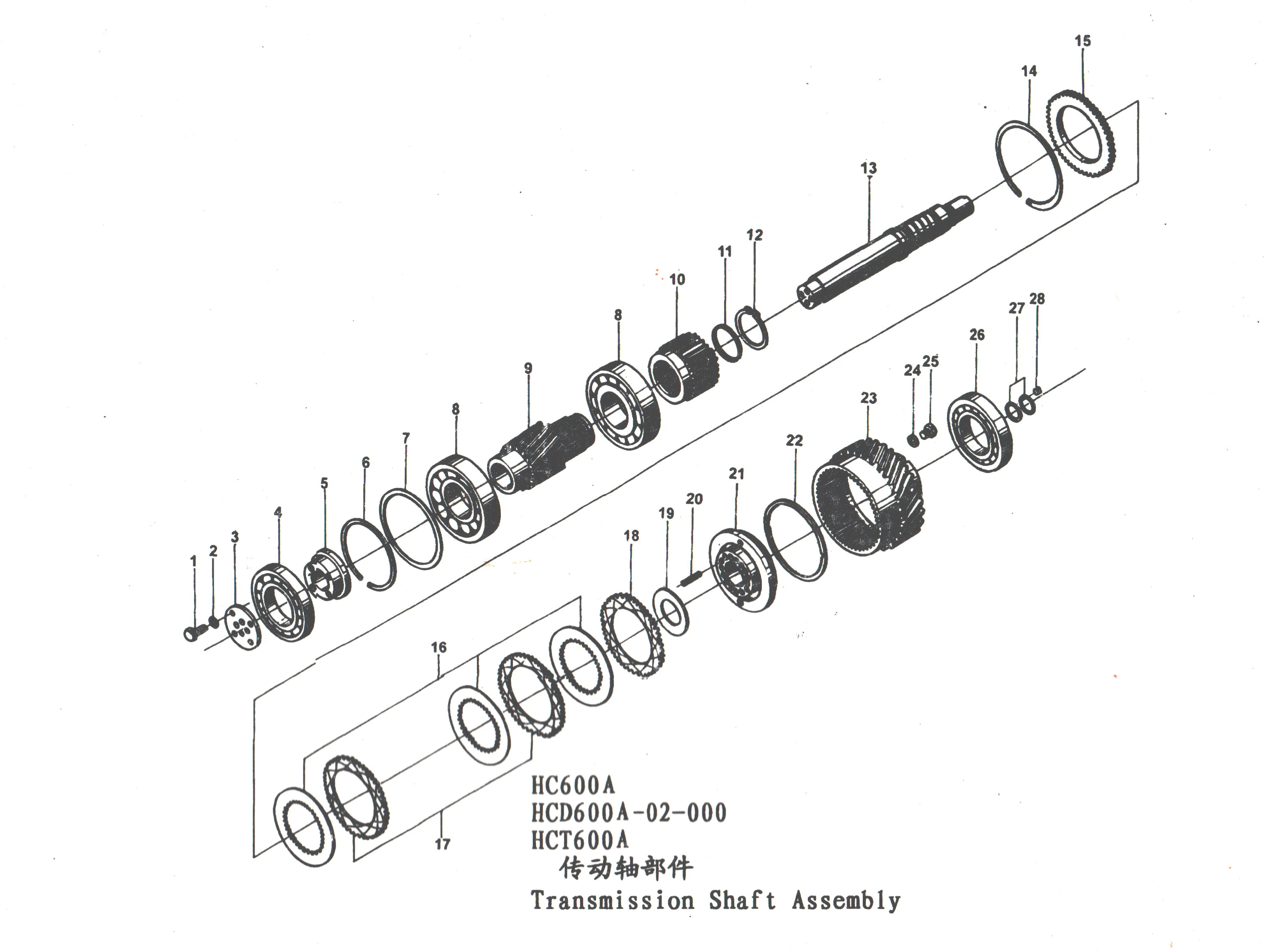
- Transmission Shaft Assembly
- Output Shaft Assembly
- Oil pipe Assembly
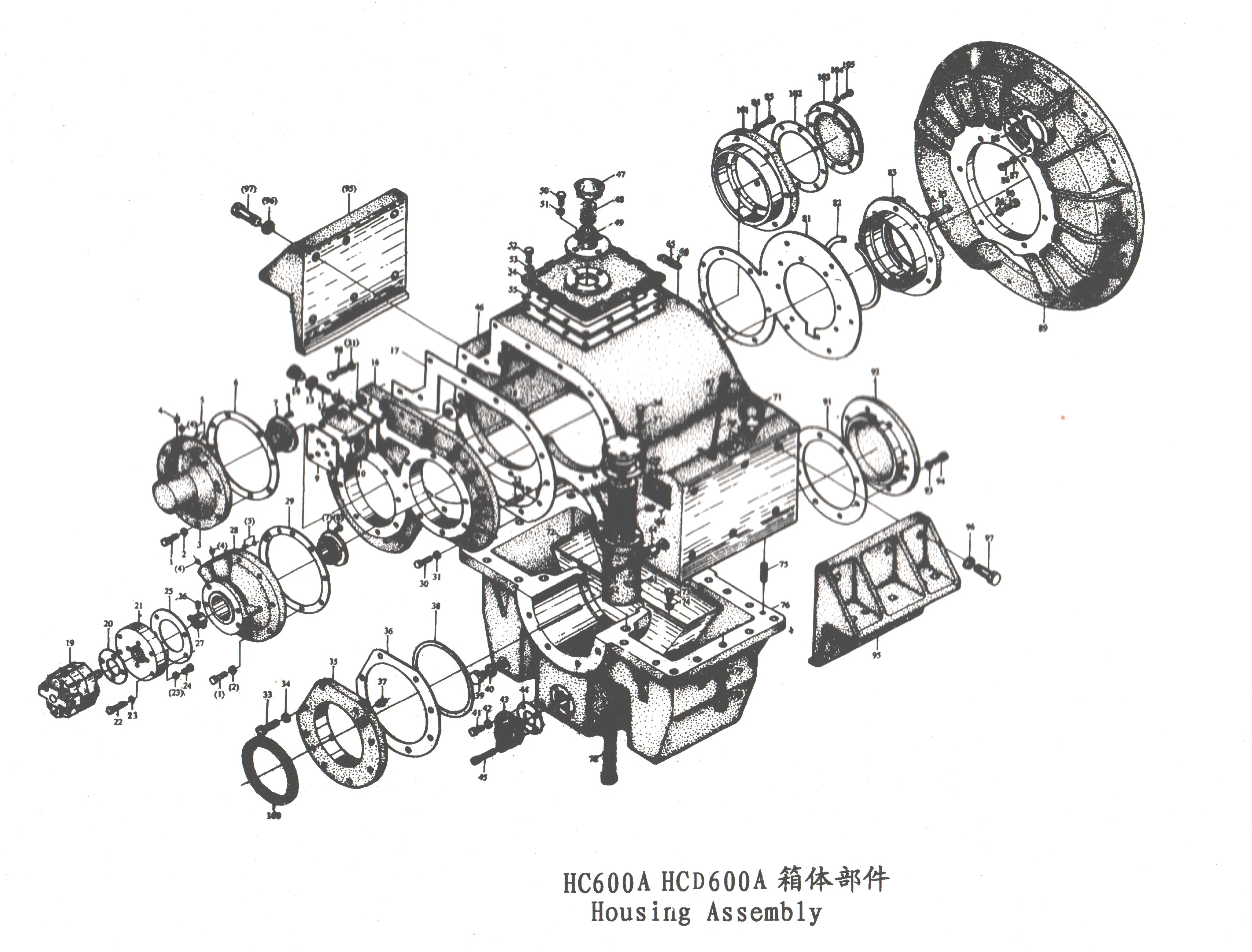
- Housing Assembly
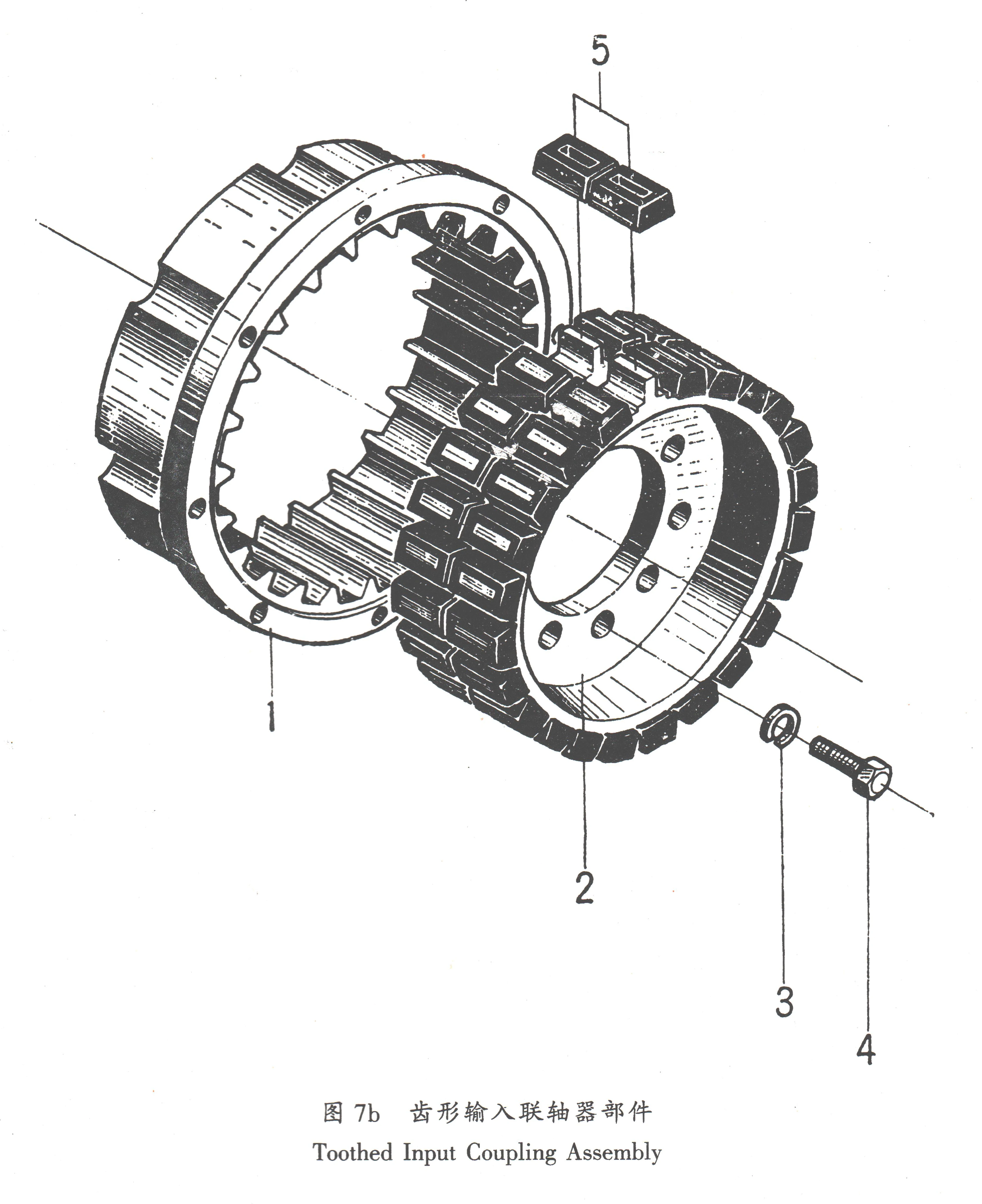
- Toothed Input Coupling Assembly
- Cooler Assembly
No. |
Part Name |
Part No. |
Qty. |
Remarks |
| 1 | Bolt | M20×55GB5783 – 86 | 10 | / |
| 2 | Washer | 20GB93 – 87 | 10 | / |
| 3 | Input Coupling | HC600A – 01 – 001 | 1 | / |
| 4 | Splashing Pan | HC600 – 01 – 002 | 1 | / |
| 5 | Bearing | 6224 GB/T276 – 94 | 1 | / |
| 6 | Snap Ring | 120 GB894.1 – 86 | 1 | / |
| 7 | Holding Ring | HC600 – 01 – 011 | 1 | / |
| 8 | Trimmer | HC600 – 04 – 022 | 1-3 | Spec. φ216×φ239 |
| 9 | Bearing | 30322 GB/T297 – 94 | 2 | 7322E Old Type |
| 10 | Pinion | HC600 – 01 – 003/22 | 1 | HC600A i = 3 For HCD600A i = 4.18 |
| 11 | Pinion | HC600 – 01 – 003/21 | 1 | HCD600A i = 4.43 For HCT600A i = 6 |
| 12 | Pinion | HC600 – 01 – 003/20 | 1 | HCD600A i = 4.7 For HCT600A i = 6.5 |
| 13 | Pinion | HC600 – 01 – 003/19 | 1 | HC600A i = 3.5 For HCD600A i = 5 For HCT600A i = 7, 8 |
| 14 | Pinion | HC600 – 01 – 003/18 | 1 | HCD600A i = 5.44 For HCT600A i = 7.5, 8.66 |
| 15 | Pinion | HC600 – 01 – 003/17 | 1 | “HCD600A i = 5.71 For HCT600A i = 9.35” |
| 16 | Clutch Bracket | HC600 – 01 – 005 | 1 | / |
| 17 | Spacer | HC600 – 01 – 014 | 1 | / |
| 18 | Snap Ring | 100 GB894.1 – 86 | 1 | / |
| 19 | Bolt Plug | HC600 – 01 – 016 | 1 | / |
| 20 | Input Shaft | HC600 – 01 – 004 | 1 | / |
| 21 | Snap Ring | HC600 – 01 – 006 | 1 | / |
| 22 | Thrust Plate | HC600 – 01 – 007 | 1 | / |
| 23 | Internal Disc | MB450 – 01 – 014 | 9 | / |
| 24 | External Disc | MB450 – 01 – 013 | 8 | / |
| 25 | Single – face Ex. Disc | HC600 – 01 – 018 | 1 | / |
| 26 | Spring Carrier | HC600A – 01 – 007 | 1 | / |
| 27 | Spring | HC600A – 01 – 009A | 16 | / |
| 28 | Piston | HC600A – 01 – 006A | 1 | / |
| 29 | Piston Ring | HC600 – 01 – 009 | 1 | / |
| 30 | Right – hand Transmission Gear | HC600A – 01 – 005 | 1 | / |
| 31 | Copper Washer | 14 Q20 – 03 | 3 | / |
| 32 | Bolt | M14×20GB5783 – 86 | 3 | / |
| 33 | Bearing | NJ224E GB/T283 – 94 | 1 | / |
| 34 | Sealing Ring | HC600 – 01 – 013 | 2 | / |
| 35 | Nut | HC600 – 01 – 017 | 1 | / |
| ——END—— | ||||
No. |
Part Name |
Part No. |
Qty. |
Remarks |
| 1 | Bolt | M12×40GB5783 – 86 | 8 | / |
| 2 | Washer | 12GB93 – 87 | 8 | / |
| 3 | Shaft End Pressure Plate | HC600A – 02 – 001 | 1 | / |
| 4 | Bearing | 6224 GB/T276 – 94 | 1 | / |
| 5 | Bearing Bracket | HC600A – 02 – 003 | 1 | / |
| 6 | Snap Ring | HC600 – 01 – 011 | 1 | / |
| 7 | Adjusting Ring | HC600 – 04 – 022 | 0-3 | Spec. φ216×φ239 |
| 8 | Bearing | 30322 GB/T297 – 94 | 2 | 7322E Old Type |
| 9 | Pinion | HC600 – 01 – 003/22 | 1 | HC600A i = 3 For HCD600A i = 4.18 |
| 10 | Pinion | HC600 – 01 – 003/21 | 1 | HCD600A i = 4.43 For HCT600A i = 6 |
| 11 | Pinion | HC600 – 01 – 003/20 | 1 | HCD600A i = 4.7 For HCT600A i = 6.5 |
| 12 | Pinion | HC600 – 01 – 003/19 | 1 | HC600A i = 3.5 For HCD600A i = 5 For HCT600A i = 7, 8 |
| 13 | Pinion | HC600 – 01 – 003/18 | 1 | HCD600A i = 5.44 For HCT600A i = 7.5, 8.66 |
| 14 | Pinion | HC600 – 01 – 003/17 | 1 | HCD600A i = 5.71 For HCT600A i = 9.35 |
| 15 | Clutch Bracket | HC600 – 01 – 005 | 1 | / |
| 16 | Spacer | HC600 – 01 – 014 | 1 | / |
| 17 | Snap Ring | 100 GB894.1 – 86 | 1 | / |
| 18 | Transmission Shaft | HC600A – 02 – 004 | 1 | / |
| 19 | Snap Ring | HC600 – 01 – 006 | 1 | / |
| 20 | Thrust Plate | HC600 – 01 – 007 | 1 | / |
| 21 | Internal Disc | MB450 – 01 – 014 | 9 | / |
| 22 | External Disc | MB450 – 01 – 013 | 8 | / |
| 23 | Single – face Ex. Disc | HC600 – 01 – 018 | 1 | / |
| 24 | Spring Carrier | HC600A – 01 – 007 | 1 | / |
| 25 | Spring | HC600A – 01 – 009A | 16 | / |
| 26 | Piston | HC600A – 01 – 006A | 1 | / |
| 27 | Piston Ring | HC600 – 01 – 009 | 1 | / |
| 28 | Left – hand Transmission Gear | HC600A – 02 – 005 | 1 | / |
| 29 | Copper Washer | Q20 – 03 | 3 | / |
| 30 | Bolt | M14×20GB5783 – 86 | 3 | / |
| 31 | Bearing | NJ224E GB/T283 – 94 | 1 | / |
| 32 | Sealing Ring | HC600 – 01 – 013 | 2 | / |
| 33 | Nut | HC600 – 01 – 017 | 1 | / |
| ——END—— | ||||
No. |
Part Name |
Part No. |
Qty. |
Remarks |
| 1 | Bearing | NJ2224 GB/T283 – 94 | 1 | / |
| 2 | Driven Gear | HC600 – 03 – 102/58 | 1 | i = 2:1 |
| 3 | Driven Gear | HC600 – 03 – 102/62 | 1 | i = 2.5:1 |
| 4 | Driven Gear | HC600 – 03 – 102/66 | 1 | i = 3:1 |
| 5 | Driven Gear | HC600 – 03 – 102/68 | 1 | i = 3.5:1 |
| 6 | Driven Gear | HC600 – 03 – 102/70 | 1 | i = 4:1 |
| 7 | Driven Gear | HCD600 – 03 – 102/92 | 1 | i = 4.18:1 |
| 8 | Driven Gear | HCD600 – 03 – 102/93 | 1 | i = 4.43:1 |
| 9 | Driven Gear | HCD600 – 03 – 102/94 | 1 | i = 4.7:1 |
| 10 | Driven Gear | HCD600 – 03 – 102/95 | 1 | i = 5.0:1 |
| 11 | Driven Gear | HCD600 – 03 – 102/98 | 1 | i = 5.44:1 |
| 12 | Driven Gear | HCD600 – 03 – 102/97 | 1 | i = 5.71:1 |
| 13 | Output Shaft | HC600 – 03 – 101 | 1 | / |
| 14 | Spacer | HC600 – 03 – 001 | 1 | / |
| 15 | Bearing | 32228 GB/T297 – 94 | 2 | / |
| 16 | Output Coupling | HC600 – 03 – 002 | 1 | / |
| 17 | O – ring | φ128×5.3 GB3452.1 – 92 | 1 | / |
| 18 | Plate | MB450 – 03 – 002 | 1 | / |
| 19 | Lock Plate | MB450 – 03 – 006 | 1 | / |
| 20 | Bolt | M24×45 GB5783 – 86 | 3 | / |
| ——END—— | ||||

No. |
Part Name |
Part No. |
Qty. |
Remarks |
| 1 | Bolt | M12×45 GB5783 – 86 | 16 | / |
| 2 | Washer | 12 GB93 – 87 | 16 | / |
| 3 | Rear End Cover | HC600A – 04 – 003 | 1 | / |
| 4 | Plug | φ10 Q21 – 38 | 4 | / |
| 5 | O – ring | 16×2.4 GB1235 – 76 | 4 | / |
| 6 | Gasket | HC600 – 04 – 028 | 1 | / |
| 7 | Distribute Bush | HC600 – 04 – 029 | 2 | / |
| 8 | Screw | M6×14 GB68 – 85 | 6 | / |
| 9 | Upper Gasket | HC600 – 04 – 002 | 1 | / |
| 10 | Inlet Board | HC600 – 04 – 004 | 1 | Use When Manual Controlling |
| 11 | Inlet Board | HC600 – 04 – 004X1 | 1 | Use astern as ahead |
| 12 | Inlet Board | HCD600 – 04 – 004 | 1 | Use When Electromagnetic Controlling |
| 13 | Lubrication Valve | HC600 – 04 – 033 | 1 | / |
| 14 | Spring | 1.4×10×35 GB2089 – 80 | 1 | / |
| 15 | Copper Washer | 20 Q20 – 03 | 1 | / |
| 16 | Bolt | HC600 – 04 – 034 | 1 | / |
| 17 | Lower Gasket | HC600 – 04 – 003 | 1 | / |
| 18 | Rear Housing Cover | HCD600A – 04 – 103 | 1 | upply as a group with upper and lower housings |
| 19 | Gasket | HCD600 – 04 – 024 | 1 | / |
| 20 | Sprayer Group | HC600A – 04 – 200 | 1 | / |
| 21 | Oil Pump | BB – B63A – 2 | 1 | / |
| 22 | Oil Pump Gasket | HC600 – 04 – 007 | 1 | / |
| 23 | Connecting Plate | HC600 – 04 – 032 | 1 | / |
| 24 | Bolt | M8×50 GB5783 – 86 | 4 | / |
| 25 | Washer | 8 GB93 – 87 | 8 | / |
| 26 | Bolt | M8×25 GB5783 – 86 | 4 | / |
| 27 | Gasket | HC600 – 04 – 031 | 1 | / |
| 28 | Screw | M6×10 GB73 – 85 | 1 | / |
| 29 | Pump Coupling | HC600 – 04 – 030 | 1 | / |
| 30 | Rear End Cover | HC600A – 04 – 002 | 1 | / |
| 31 | Gasket | HC600 – 04 – 027 | 1 | / |
| 32 | Bolt | M12×45 GB5783 – 86 | 13 | / |
| 33 | Washer | 12 GB93 – 87 | 14 | / |
| 34 | Pin | B16×50 GB118 – 86 | 2 | / |
| 35 | Bolt | M16×60 GB5782 – 86 | 8 | / |
| 36 | Washer | 16 GB93 – 87 | 8 | / |
| 37 | Rear End Cover | HCD600 – 04 – 020 | 1 | / |
| 38 | Gasket | HCD600 – 04 – 021 | 1 | / |
| 39 | Oil Cup | M10×1 GB1152 – 79 | 1 | / |
| 40 | Regulating Plate | HC600 – 04 – 022 | 1-2 | Spec. φ226×φ249 |
| 41 | Drain Plug | M22 Q21 – 15 | 1 | / |
| 42 | Copper Washer | 22 Q20 – 03 | 1 | / |
| 43 | Bolt | M8×25 GB5783 – 86 | 2 | / |
| 44 | Washer | 8 GB93 – 87 | 2 | / |
| 45 | Suction Pipe Flange | T300 – 04 – 016 | 1 | / |
| 46 | Filter Gasket | 300 – 04 – 204 | 1 | / |
| 47 | Hexigon Screw | M8×60 GB70 – 85 | 2 | / |
| 48 | Upper Housing | HCD600A – 04 – 101 | 1 | Supply as a group with lower housing and rear housing |
| 49 | Breather Cover | MB450 – 04 – 501 | 1 | / |
| 50 | Breather Stem | MB450 – 04 – 503 | 2 | / |
| 51 | Breather Carrier | MB450 – 04 – 502 | 1 | / |
| 52 | Bolt | M8×30 GB5783 – 86 | 4 | / |
| 53 | Washer | 8 GB93 – 87 | 4 | / |
| 54 | Bolt | M8×25 GB5783 – 86 | 12 | / |
| 55 | Washer | 8 GB93 – 87 | 12 | / |
| 56 | Cover Plate | HC600 – 04 – 005 | 1 | / |
| 57 | Gasket | HC600 – 04 – 006 | 1 | / |
| 58 | Bolt | M8×25 GB5783 – 86 | 4 | / |
| 59 | Washer | 8 GB93 – 87 | 4 | / |
| 60 | Strainer Cover | T300 – 04 – 022 | 1 | / |
| 61 | Gasket | MB270 – 04 – 302A | 1 | / |
| 62 | Filter | WU – 100×180 – J | 1 | / |
| 63 | Filter Case | T300 – 04 – 021 | 1 | / |
| 64 | Bolt | M12×70 GB5782 – 86 | 2 | / |
| 65 | Washer | 12 GB93 – 87 | 2 | / |
| 66 | Spacer Block | HCT600 – 04 – 010 | 2 | / |
| 67 | Steering Plate | Q25 – 06 | 1 | / |
| 68 | Rivet | 2×6 GB827 – 86 | 6 | / |
| 69 | Straight Pin | 3×20 GB119 – 86 | 1 | / |
| 70 | Dipstick Handle | 135 – 04 – 601 | 1 | / |
| 71 | O – ring | 16×2.4 GB1235 – 76 | 1 | / |
| 72 | Dipstick | HCD320 – 04 – 201 | 1 | / |
| 73 | Eye Screw | M24 GB825 – 88 | 1 | / |
| 74 | Splash Cover | HCD600 – 04 – 010 | 1 | / |
| 75 | Bolt | M10×20 GB5783 – 86 | 4 | / |
| 76 | Washer | 10 GB93 – 87 | 4 | / |
| 77 | Pin | B16×50 GB118 – 86 | 2 | / |
| 78 | Lower Housing | HCD600 – 04 – 102 | 1 | Supply as a group with upper housing and rear housing |
| 79 | Washer | 24 GB93 – 87 | 4 | / |
| 80 | Bolt | M24×180 GB5782 – 86 | 4 | / |
| 81 | Washer | 20 GB93 – 87 | 18 | / |
| 82 | Bolt | M20×75 GB5782 – 86 | 18 | / |
| 83 | Case Gasket | HCD600 – 04 – 018 | 1 | / |
| 84 | Holding Ring | HC600 – 01 – 011 | 1 | / |
| 85 | Front Cover | HC600A – 01 – 002 | 1 | / |
| 86 | Washer | 12 GB93 – 87 | 21 | / |
| 87 | Bolt | M12×55 GB5783 – 86 | 8 | / |
| 88 | Screw | M6×12 GB67 – 76 | 2 | / |
| 89 | Washer | 6 GB93 – 87 | 2 | / |
| 90 | Cover Plate | 1601 – 0018 | 1 | / |
| 91 | Bell Housing (00#) | HCD600A – 04 – 001X₅ | 1 | For SAE 21″ flywheel |
| 92 | Bell Housing (0#) | HCD600A – 04 – 001X₁ | 1 | For SAE 16″/18″ flywheel |
| 93 | Bell Housing (1d) | HCD600A – 04 – 001X₂ | 1 | / |
| 94 | Bell Housing (00#) | HCD600A – 04 – 001X₃ | 1 | For SAE 16″/18″ flywheel |
| 95 | Bell Housing (0#) | HCD600A – 04 – 001X₄ | 1 | For SAE 14″ flywheel |
| 96 | Bell Housing (00#) | HCD600A – 04 – 001X₅ | 1 | For SAE 21″ flywheel |
| 97 | Front Cover Gasket | HC600 – 04 – 012 | 1 | / |
| 98 | Front Cover | HC600 – 04 – 011 | 1 | / |
| 99 | Washer | 12 GB93 – 87 | 8 | / |
| 100 | Bolt | M12×35 GB5783 – 86 | 8 | / |
| 101 | Supporter | HC600 – 04 – 009 | 2 | / |
| 102 | Washer | 24 GB93 – 87 | 12 | / |
| 103 | Bolt | M24×65 GB5783 – 86 | 12 | / |
| 104 | Bolt | M12×55 GB70 – 85 | 1 | / |
| 105 | Pin | HC600 – 04 – 001 | 1 | / |
| 106 | Cased Seal | PD170×200×16 JB2600 – 80 | 2 | / |
| 107 | Front End Cover | HC600A – 02 – 002 | 1 | / |
| 108 | Front Cover Gasket | HCT500A – 04 – 011 | 1 | / |
| 109 | Front Cover Plate | HCT600A – 04 – 010 | 1 | / |
| 110 | Washer | 6GB93 – 87 | 8 | / |
| 111 | Bolt | M6×20GB5783 – 86 | 8 | / |
| 112 | Nameplate | 100×100Q25 – 13 | 1 | / |
| ——END—— | ||||
No. |
Part Name |
Part No. |
Qty. |
Remarks |
| 1 | Internal Toothed Ring | Q05 – 17X₁ – 02 | 1 | / |
| 2 | External Toothed Ring | Q05 – 17X₁ – 01 | 1 | / |
| 3 | Washer | 20GB93 – 76 | 10 | / |
| 4 | Bolt | M20×45GB5783 – 86 | 10 | / |
| 5 | Toothed Rubber Block | Q26 – 06 – 03 | 48 | / |
| ——END—— | ||||
No. |
Part No. |
Part Name |
Qty. |
Remarks |
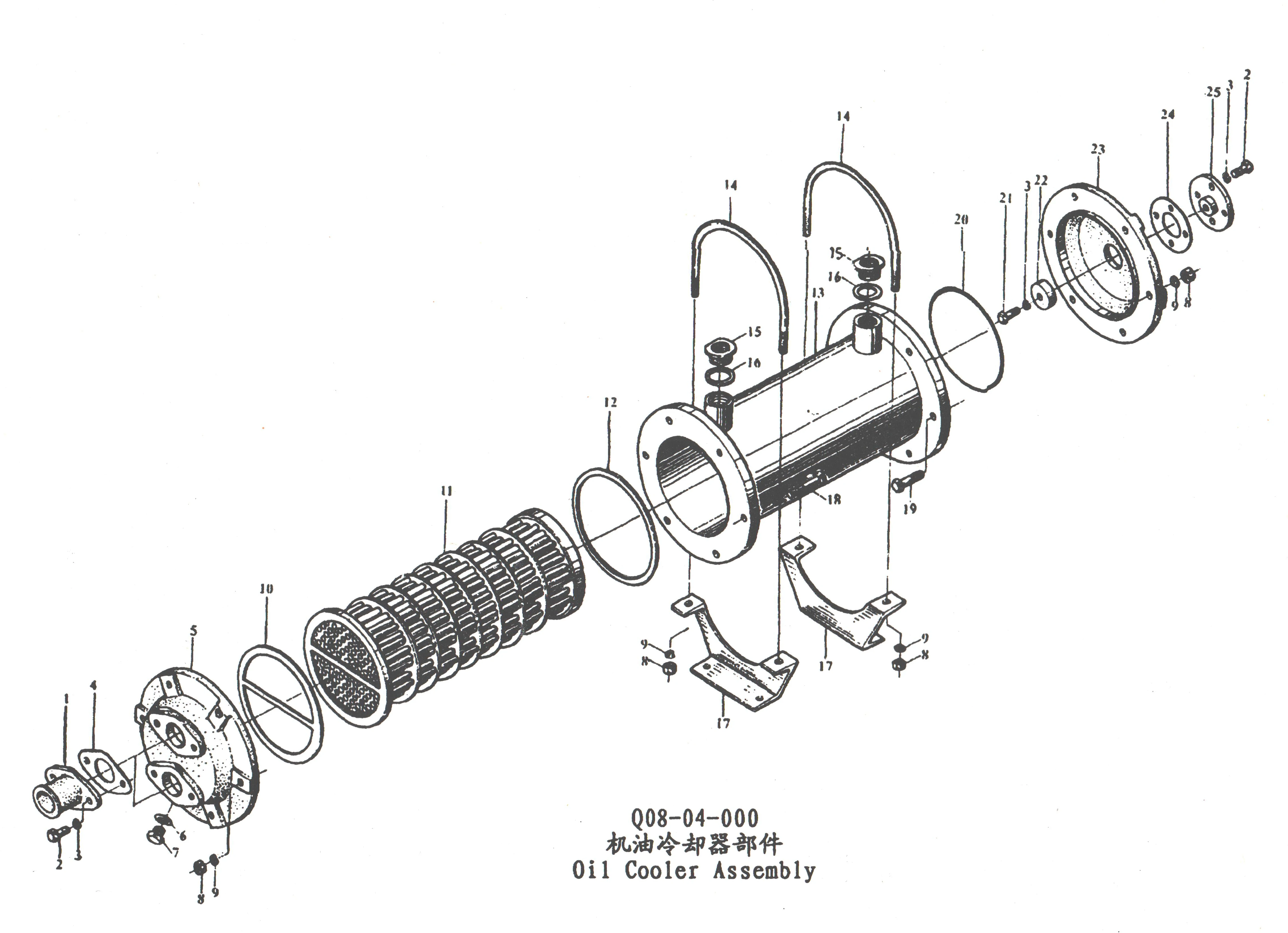
| 1 | Q08 – 04 – 11 | Inlet and Outlet Joint | 2 | / |
| 2 | GB5782 – 86 | M8x20 Bolt | 8 | / |
| 3 | GB93 – 87 | Washer 8 | 9 | / |
| 4 | Q08 – 04 – 10 | Gasket | 2 | / |
| 5 | Q08 – 04 – 01 | Front Cover | 1 | / |
| 6 | Q20 – 23 | Copper Washer 14 | 1 | / |
| 7 | Q20 – 01 | M14x1.5 Plug | 1 | / |
| 8 | GB6170 – 86 | M10 Nut | 16 | / |
| 9 | GB93 – 87 | Washer 10 | 16 | / |
| 10 | Q08 – 04 – 02 | Gasket | 1 | / |
| 11 | Q08 – 04 – 100 | Cooler Assembly | 1 | / |
| 12 | Q08 – 04 – 03 | Gasket | 1 | / |
| 13 | Q08 – 04 – 200 | Case Assembly | 1 | / |
| 14 | Q08 – 04 – 09 | Holddown Bolt | 2 | / |
| 15 | Q08 – 04 – 12 | Coupling Sleeve | 2 | / |
| 16 | Q20 – 03 | Copper Washer 27 | 2 | / |
| 17 | Q08 – 04 – 08 | Supporter | 2 | / |
| 18 | GB5782 – 86 | M10x55 Bolt | 6 | / |
| 19 | GB5782 – 86 | M10x50 Bolt | 6 | / |
| 20 | GB3452.1 – 82 | “O” – ring 14.5×7 | 1 | / |
| 21 | GB5782.1 – 86 | M8x25 Bolt | 1 | / |
| 22 | Q08 – 04 – 07 | Spelter | 1 | / |
| 23 | Q08 – 04 – 04 | Rear Cover | 1 | / |
| 24 | Q08 – 04 – 05 | Bottom Plate | 1 | / |
| 25 | Q08 – 04 – 06 | Cover | 1 | / |
| ——END—— | ||||
Note: All Above Data are Just for Reference, All Data Might Change Without Notices or Updates, Please Contact Our Sales Team to Confirm All Details Via WhatsApp or Email.

Engine Sale Manual

Installation Drawing

Installation Manual

Operation Manual

Parts Catalogue

Report & Certifcate
Tags: