The speed input range of the Advance 40A marine gearbox is 750-2000 RPM, with engine input power from 40 kW to 58.8 kW. the center distance is 142 mm, the reduction ratio range is 2.07-3.83, the transmission capacity range is 0.02-0.0294 kW/RPM, the rated propeller thrust is 8.8 KN, and the input shaft is in the train Opposite to the output shaft.
Advance 40A marine gearbox is composed of transmission shaft, output coupling, input coupling, oil pressure gauge, oil Filter, control system, oil pump and other important components.
Advance 40A marine gearboxes provides two types of control system which are push-pull flexible shaft, electric control for customers to choose. To meet the different requirement of coupling with different engine brand and models, Advance 40A marine gearboxes provide different SAE size coupling and housing including SAE 1 2 3, flywheel SAE 14 11.5 is available……
All of our Advance 40A series marine gearbox can provide CCS classification certificate, some of series can provide international classifications with extra costs which mainly including French BV, British LR, American ABS, Japanese NK , Norway DNV-GL, Russia RS, South Korea KR, Italy RINA and other classification societies.
Advantages Of Advance 40A Marine Gearbox Parts
-
It has the functions of reversing, clutching, and deceleration, and can be matched with various marine diesel engines with equivalent torque to form a unit. Applicable to all kinds of medium and small ships.
-
The gearbox has a compact structure and can be controlled by a variety of control methods. The operation is light and sensitive, and it can be operated from a distance, which is convenient for driving and machine integration.
-
The advanced design makes the connection of the gearbox very soft, easy to maintain, more durable, and has the characteristics of large transmission power, small size and light weight.
-
The toothed elastic input coupling and connection cover can be matched with various flywheels and flywheel shells to connect with the host, easy installation and beautiful appearance
-
With excellent deceleration effect and strong bearing propeller thrust
-
Professional gearbox specialists and after-sales service, spare parts directly available from stock.
Technical Specifications
| Gearbox Model: | 40A |
| Input Speed: | 750 – 2000 RPM |
| Power: | 58.8 kW @ 2000 RPM |
| Center Distance: | 142 mm |
| Trans.Capacity: | 0.0294 kW / RPM |
| Reduction Ratio: | 2.07 2.96 |
| Rated Thrust: | 8.8 kN |
| Dimension: | 490 mm * 670 mm * 620 mm |
| Net Weight: | 225 kg |
| Lead Time: | 15-30 Working Days |
| Payment Terms: | T/T ,L/C |


Search by Part No. or Part Name
Click Kit Name to Check Part List
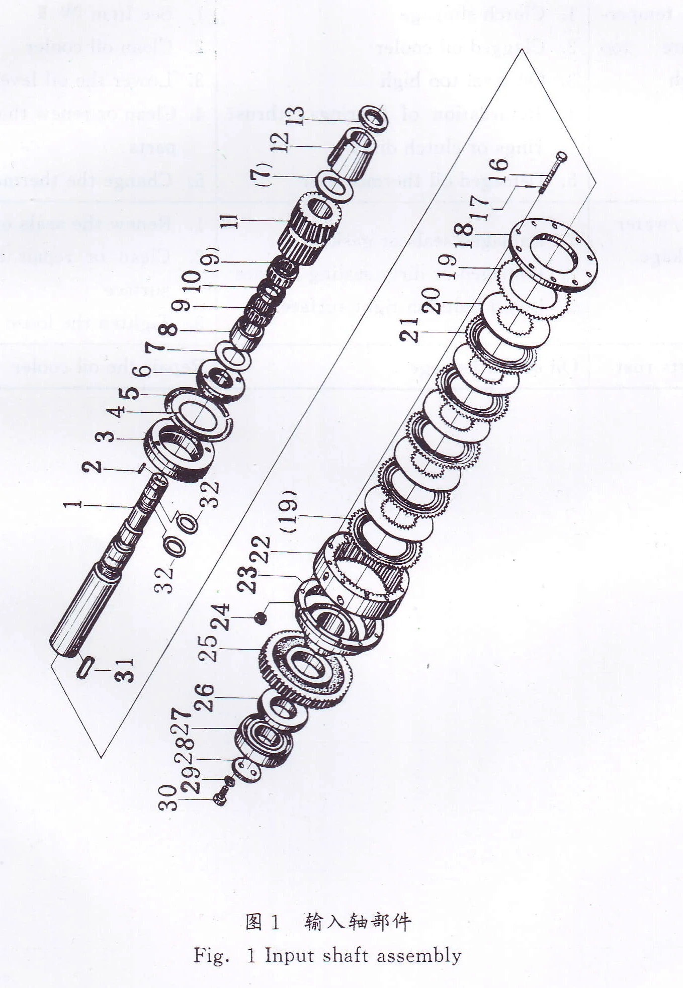
- Input Shaft Assembly
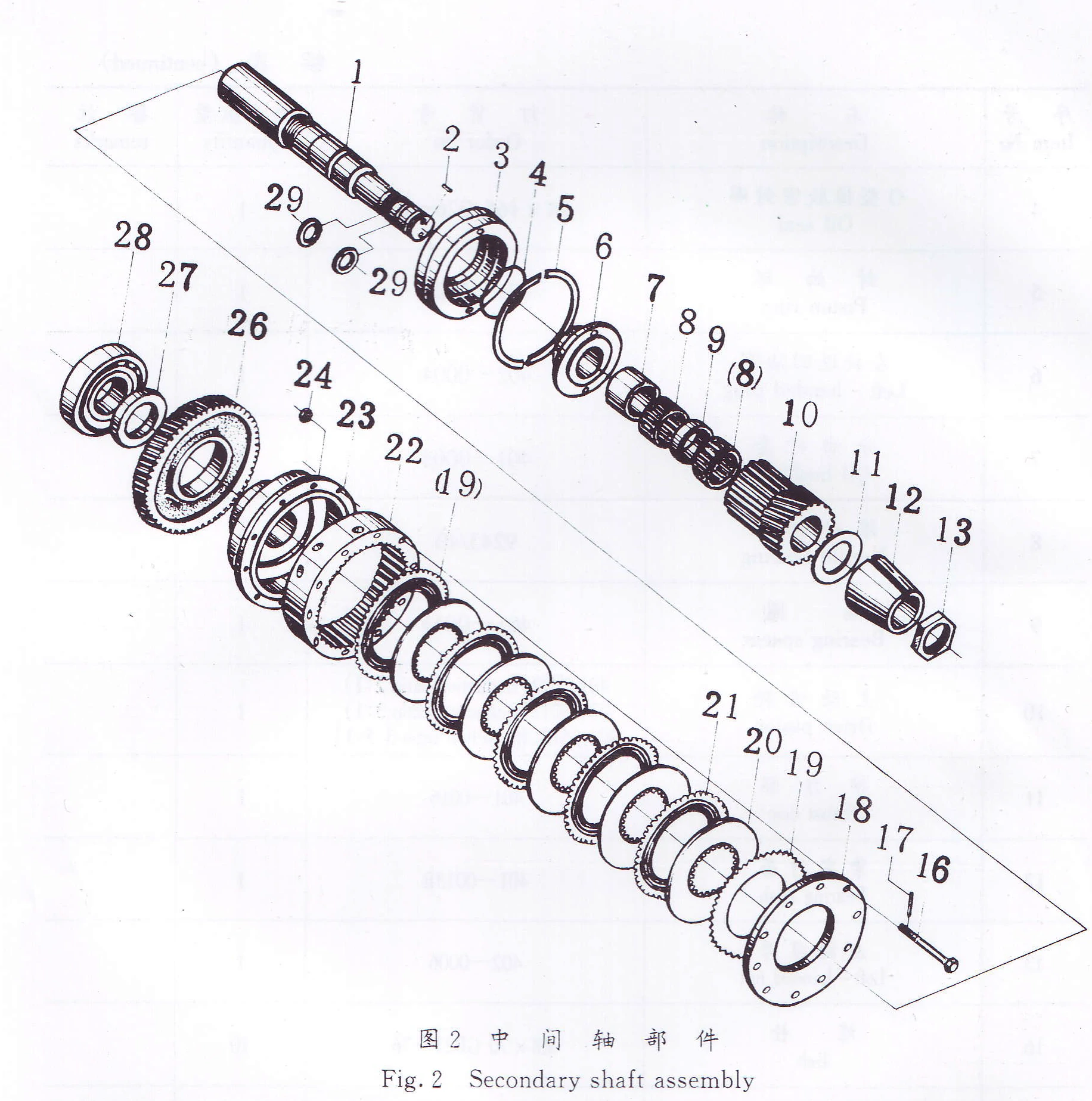
- Secondary shaft assembly
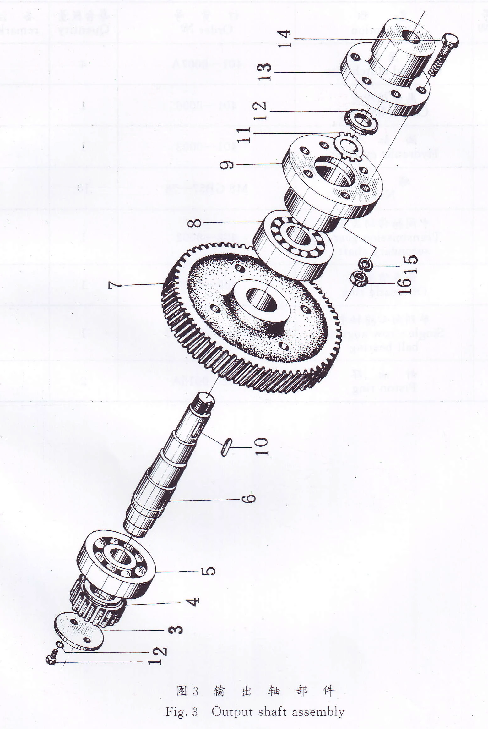
- Output Shaft Assembly
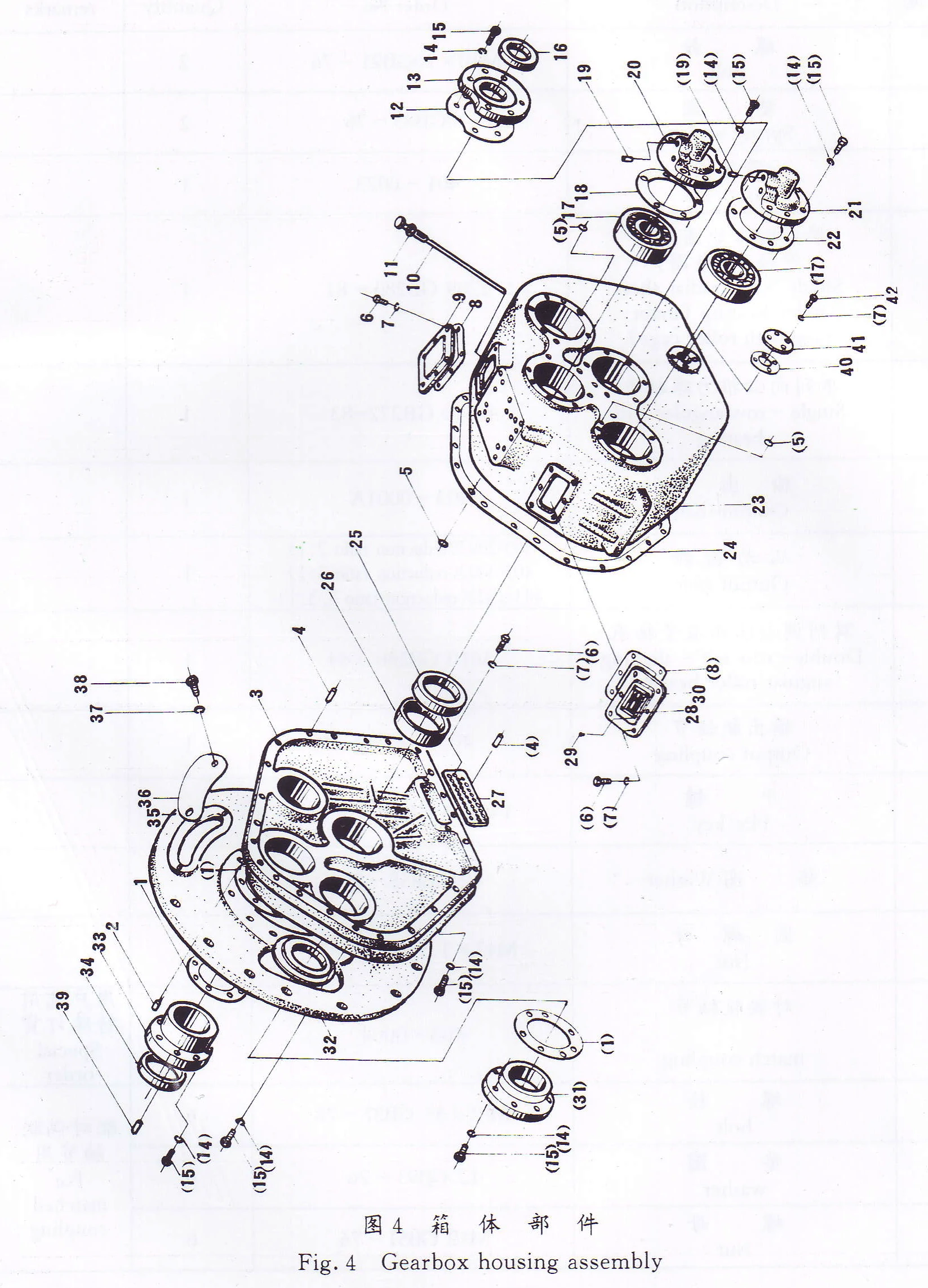
- Housing Assembly
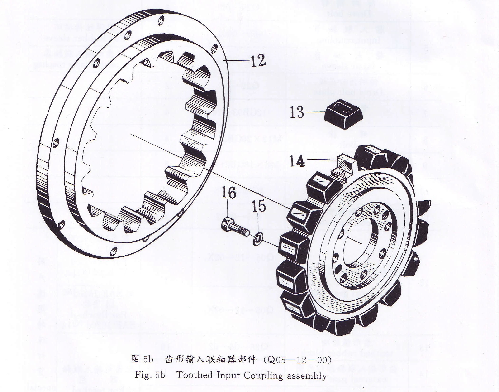
- Toothed Input Coupling Assembly
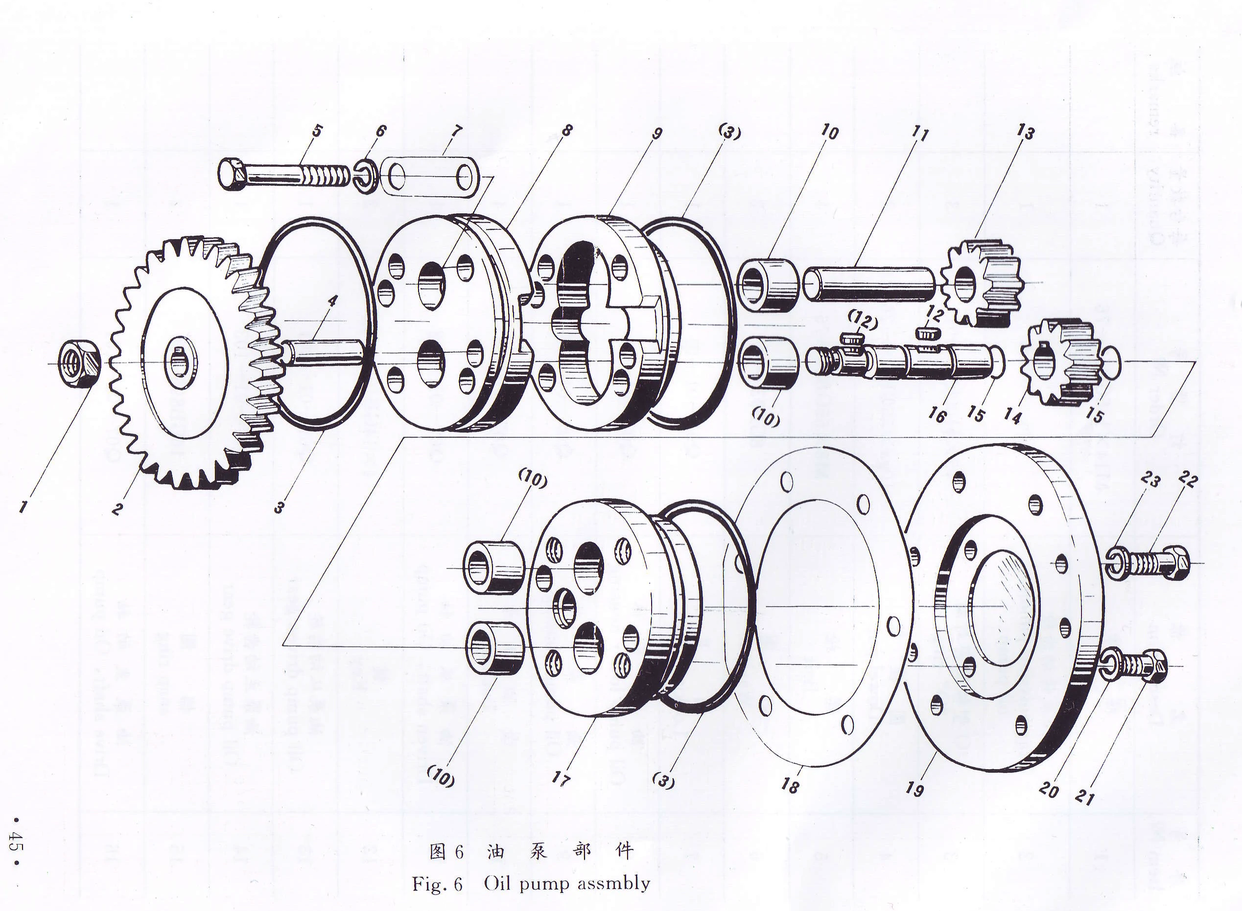
- Oil Pump Assembly
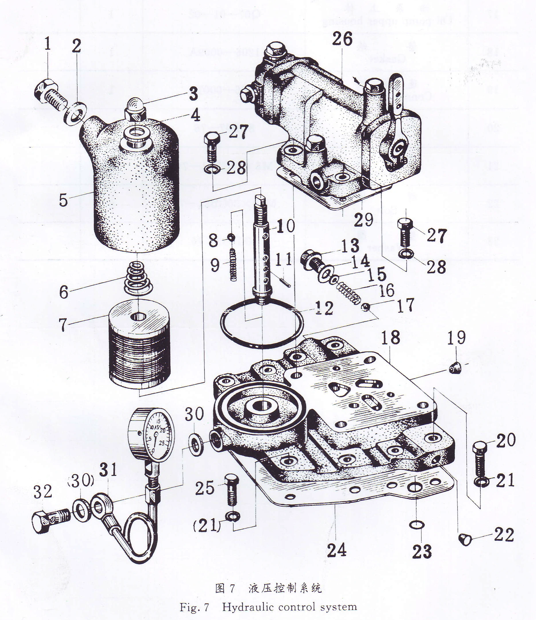
- Hydraulic Control Assembly
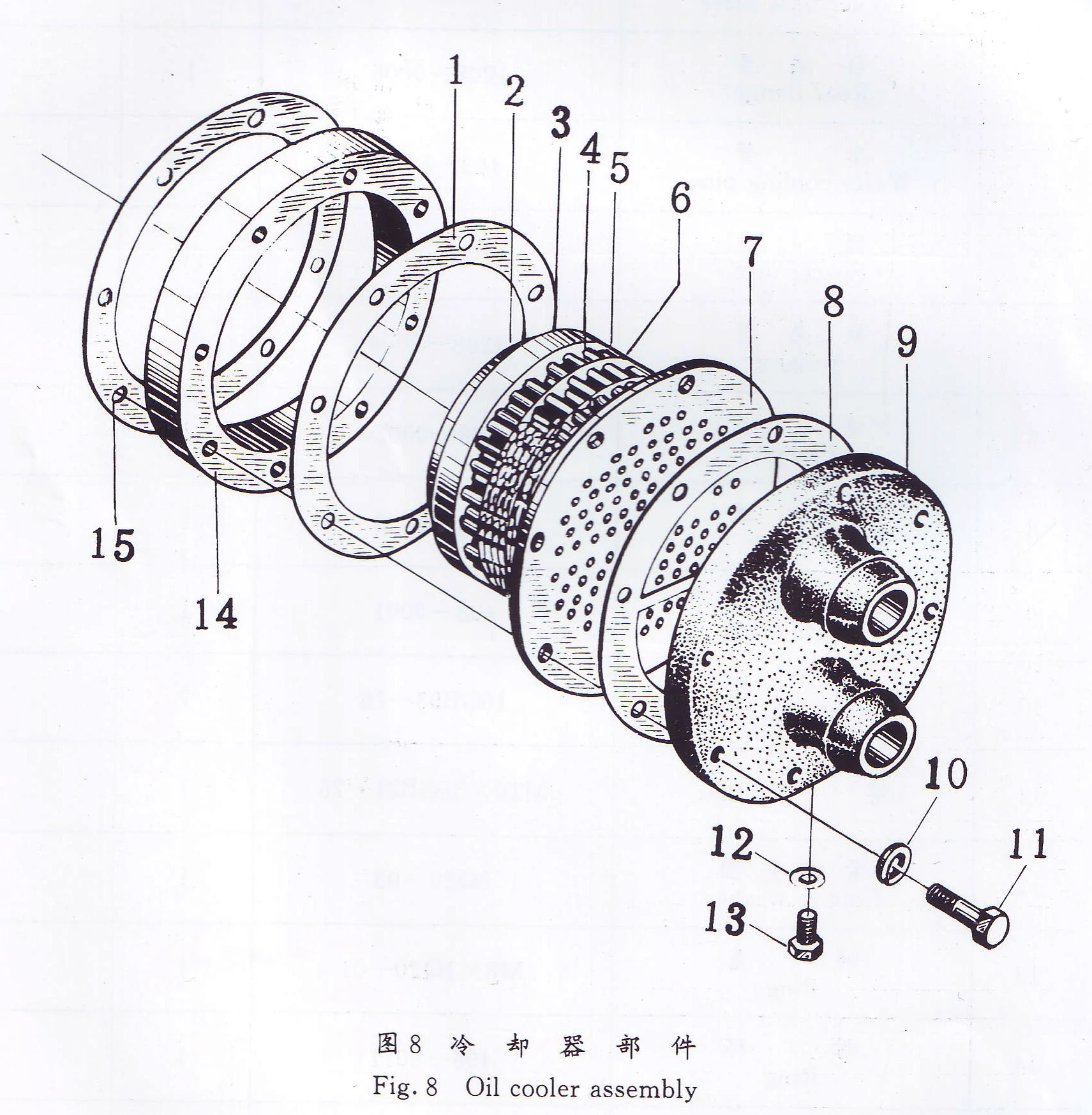
- Oil cooler Assembly
No. |
Part Name |
Part No. |
Qty. |
Remarks |
| 1 | Input shaft | 401—0001 | 1 | / |
| 2 | Plug | 401—0028 | 1 | / |
| 3 | Working piston | 401—0005 | 1 | / |
| 4 | “O” ring | φ4×φ65Q26—01 | 1 | / |
| 5 | Piston ring | 401—0025 | 1 | / |
| 6 | Right – handed oil plug | 401—0004 | 1 | / |
| 7 | Thrust disc | 401—0016 | 2 | / |
| 8 | Oil bushing | 401—0008 | 1 | / |
| 9 | Needle bearing | 9243/40 | 2 | / |
| 10 | Bearing spacer | 401—0011 | 1 | / |
| 11 | Drive pinion | 401 – 2012(reduction ratio 2:1) | 1 | / |
| 12 | Drive pinion | 401 – 3012(reduction ratio 3:1) | 1 | / |
| 13 | Drive pinion | 401 – 3512(reduction ratio 3.5:1) | 1 | / |
| 14 | Bearing bush | 401—0013B | 1 | / |
| 15 | Right – handed nut | 401—0014A | 1 | / |
| 16 | Bolt | M8×70GB23—76 | 10 | / |
| 17 | Cotter pin | 2×16GB91—76 | 10 | / |
| 18 | Thrust plate | 401—0009 | 1 | / |
| 19 | Single – face clutch disc | 401—0018 | 2 | / |
| 20 | Internal clutch disc | 401—0019 | 5 | / |
| 21 | External clutch disc | 401—0007A | 4 | / |
| 22 | Clutch housing | 401—0006 | 1 | / |
| 23 | Cylinder body | 401—0003 | 1 | / |
| 24 | Nut | M8GB57—76 | 10 | / |
| 25 | Transmission gear, input shaft | 401—0002 | 1 | / |
| 26 | Oil nozzle | 401—0026 | 1 | / |
| 27 | Single – row angular ball bearing | 36309GB292—64 | 1 | / |
| 28 | Front plate | 401—0023 | 1 | / |
| 29 | Washer | 10GB93—76 | 2 | / |
| 30 | Bolt | M10×25GB21—76 | 2 | / |
| 31 | Flat Key | 14×45GB1096—72 | 1 | / |
| 32 | Piston ring | 401—0015A | 2 | / |
| ——END—— | ||||
No. |
Part Name |
Part No. |
Qty. |
Remarks |
| 1 | Secondary shaft | 402—0001 | 1 | / |
| 2 | Plug | 401—0028 | 1 | / |
| 3 | Hydraulic piston | 401—0005 | 1 | / |
| 4 | Oil seal | φ4×φ65 Q26—01 | 1 | / |
| 5 | Piston ring | 401—0025 | 1 | / |
| 6 | Left – handed plug | 402—0004 | 1 | / |
| 7 | Qil bushing | 401—0008 | 1 | / |
| 8 | Needle bearing | 9243/40 | 2 | / |
| 9 | Bearing spacer | 401—0011 | 1 | / |
| 10 | Drive pinion | 401-2012(Reduction ratio 2:1) | 1 | / |
| 11 | Drive pinion | 401-3012(Reduction ratio 3:1) | 1 | / |
| 12 | Drive pinion | 401-3512(Reduction ratio 3.5:1) | 1 | / |
| 13 | Thrust disc | 401—0016 | 1 | / |
| 14 | Bearing bush | 401—0013B | 1 | / |
| 15 | Left – handed nut | 402—0006 | 1 | / |
| 16 | Bolt | M8×70 GB23—76 | 10 | / |
| 17 | Cotter pin | 2×16 GB91—76 | 10 | / |
| 18 | Thrust plate | 401—0009 | 1 | / |
| 19 | Single – face clutch disc | 401—0018A | 2 | / |
| 20 | Internal clutch disc | 401—0019 | 5 | / |
| 21 | External clutch disc | 401—0007A | 4 | / |
| 22 | Clutch housing | 401—0006 | 1 | / |
| 23 | Hydraulic cylinder | 401—0003 | 1 | / |
| 24 | Nut | M8 GB57—76 | 10 | / |
| 25 | Transmission gear, secondary shaft | 402—0002 | 1 | / |
| 26 | Oil nozzle ring | 402—0005 | 1 | / |
| 27 | Single – row angular ball bearing | 309 GB276-82 | 1 | / |
| 28 | Piston ring | 401—0015A | 2 | / |
| ——END—— | ||||
Part No |
Part Name |
Part No. |
Qty. |
Remarks |
| 1 | Bolt | M10×20GB21 – 76 | 2 | / |
| 2 | Spring washer | 10GB93 – 76 | 2 | / |
| 3 | Front plate | 401 – 0023 | 1 | / |
| 4 | Single – row radial short roller bearing (inner race with roller cage) | 2209 GB283 – 81 | 1 | / |
| 5 | Single – row angular ball bearing | 46310 GB272-83 | 1 | / |
| 6 | Output shaft | 403 – 0001A | 1 | / |
| 7 | Output gear | 403-2002(reduction ratio 2:1) | 1 | / |
| 8 | Output gear | 403-3002(reduction ratio 3:1) | 1 | / |
| 9 | Output gear | 403-3502(reduction ratio 3.5:1) | 1 | / |
| 10 | Double – row self – aligning angular roller bearing | 3610 GB286 – 64 | 1 | / |
| 11 | Output coupling | 403 – 0003A | 1 | / |
| 12 | Flat key | 14×45 GB1096 – 79 | 1 | / |
| 13 | Washer | 42 GB858 – 76 | 1 | / |
| 14 | Nut | M42×1.5 GB812-76 | 1 | / |
| 15 | Match coupling | 403 – 0004 | 1 | Special order for user selection |
| 16 | Bolt | M12×55 GB27 – 76 | 6 | For matched coupling |
| 17 | Washer | 12 GB93 – 76 | 6 | For matched coupling |
| 18 | Nut | M12 GB51 – 76 | 6 | For matched coupling |
| ——END—— | ||||
No. |
Part Name |
Part No. |
Qty. |
Remarks |
| 1 | Gasket | 404—0011 | 2 | / |
| 2 | Plug | φ12Q21—13 | 1 | / |
| 3 | Gearbox cover | 404—0001 | 1 | / |
| 4 | Tapered pin, inside threaded at end | 12×35GB118—76 | 2 | / |
| 5 | Seal ring | φ2×φ16Q26—01 | 6 | / |
| 6 | Hexagonal Bolt | M8×12GB21—76 | 14 | / |
| 7 | Spring washer | 8GB93—76 | 18 | / |
| 8 | Gasket | 404—0004 | 2 | / |
| 9 | Top cover plate | 404—0006 | 1 | / |
| 10 | Oil dipstick | 404—0025 | 1 | / |
| 11 | Handle, dip – stick | Q26—02 | 1 | / |
| 12 | Gasket | 404—0017 | 1 | / |
| 13 | Rear Cover. output shaft | 404—0016 | 1 | / |
| 14 | Washer | 10GB93—76 | 52 | / |
| 15 | Hexagonal head bolt | M10×30GB21—76 | 48 (46 for coupling housing) | / |
| 16 | Hexagonal head bolt | M10×35GB21—76 (for coupling housing) | 6 (for coupling housing) | / |
| 17 | Oil sealing | φ50×φ70×12HG4—692—67 | 1 | / |
| 18 | Double – row self – aligning angular roller bearing | 113610GB286-87 | 2 | / |
| 19 | Gasket | 404—0012 | 1 | / |
| 20 | Plug | φ7Q21—14 | 4 | / |
| 21 | Rear end cover, input shaft | 404—0014 | 1 | / |
| 22 | Rear end cover, secondary shaft | 404—0022 | 1 | / |
| 23 | Gasket | 404—0021 | 1 | / |
| 24 | Gearbox housing | 404—0003A | 1 | / |
| 25 | Gasket | 404—0002 | 1 | / |
| 26 | Thrust ring | 404—0007 | 1 | / |
| 27 | Single – row radial short roller bearing (outer race) | 2209GB283—64 | 1 | / |
| 28 | Strainer plate | 1204—0018 | 1 | / |
| 29 | Name plate | Q25—01—01 | 1 | / |
| 30 | Rivet | 2×4GB827—76 | 4 | / |
| 31 | Cover plate | 404—0028 | 1 | / |
| 32 | Front cover | 404—0019 | 1 | / |
| 33 | Spring cover | 404—0008 | 1 | Cancel when with housing |
| 34 | Front cover | 404—0009 | 1 | / |
| 35 | Front cover | 404—0032 (for coupling housing) | 1 | / |
| 36 | Oil sealing | φ45×φ62×12HG4—692—67 | 1 | / |
| 37 | Bell housing | 404—0031A | 1 | For 4110 diesel engine |
| 38 | Bell housing | 404—0036 | 1 | For SAE J617c Nº1d, for SAE J620d Nº14 |
| 39 | Bell housing | 404—0037 | 1 | SAE J617c Nº2 for J620d Nº11 |
| 40 | Bell housing | 404—0038 | 1 | SAE J617c Nº3 for SAE J620 d Nº11 |
| 41 | Cover | Q25—04 | 1 | / |
| 42 | Cover of bell housing | 1601—0018 | 1 | / |
| 43 | Washer | 6GB97—76 | 2 | / |
| 44 | Screw | M6×12GB67—76 | 2 | / |
| 45 | Screw | M6×15GB73—76 | 2 | / |
| 46 | Gasket | 404—0035 | 1 | / |
| 47 | Draining cover | 404—0034 | 1 | / |
| 48 | Bolt | M8×20GB21—76 | 4 | / |
| ——END—— | ||||
No. |
Part Name |
Part No. |
Qty. |
Remarks |
| 1 | Circlip | 24 GB894—76 | 4 | / |
| 2 | Washer | Q29—01 | 4 | / |
| 3 | Rubber sleeve | Q26—03 | 4 | / |
| 4 | Drive bolt | Q29—02 | 4 | / |
| 5 | Input coupling | 405—0001 | 1 | For Rubber sleeve |
| 6 | Input sleeve | 405—0003 | 1 | For toothed input coupling |
| 7 | Drive bolt plate | Q29—03 | 4 | / |
| 8 | Washer | 12GB93—76 | 4 | / |
| 9 | Bolt | M12×20GB21—76 | 4 | / |
| 10 | Bolt | M8×16GB21—76 | 8 | / |
| 11 | Washer | 8GB93—76 | 8 | / |
| 12 | Input coupling adapter | 405—0002 | 1 | / |
| 13 | Internal gear ring | Q05—12—02X₁ | 1 | For flywheel SAE J620d Nº11 User – selected special order |
| 14 | Internal gear ring | Q05—12—02X₂ | 1 | For flywheel SAE J620d Nº14 User – selected special order |
| 15 | Toothed rubber block | Q26—06—02 | 16 | For toothed input coupling |
| 16 | External gear ring | Q05—12—01 | 1 | For toothed input coupling |
| 17 | Washer | 12GB93—76 | 8 | For toothed input coupling |
| 18 | Nut | M12×25GB30—76 | 8 | For toothed input coupling |
| ——END—— | ||||
No. |
Part Name |
Part No. |
Qty. |
Remarks |
| 1 | Nut | M14×1.5GB53—76 | 1 | / |
| 2 | Transmission pinion, oil pump | 406—0005A | 1 | / |
| 3 | “O” ring | φ5×φ100Q26—01 | 3 | / |
| 4 | Dowel pin | 10ga×55GB119—76 | 2 | / |
| 5 | Bolt | M8×55GB21—76 | 4 | / |
| 6 | Washer | 8GB93—76 | 2 | / |
| 7 | Locking plate | Q07—01—01 | 1 | / |
| 8 | Oil pump lower housing | Q07—01—04 | 1 | / |
| 9 | Oil pump housing | Q07—01—03 | 1 | / |
| 10 | Bushing | Q07—01—05 | 4 | / |
| 11 | Driven shaft, Oil pump | Q07—01—202 | 1 | / |
| 12 | Key | 4×14GB1096—72 | 2 | / |
| 13 | Oil pump driven gear | Q07—01—201 | 1 | / |
| 14 | Oil pump drive gear | Q07—01—103 | 1 | / |
| 15 | Snap ring | 16GB895—76 | 2 | / |
| 16 | Drive shaft, Oil pump | Q07—01—101 | 1 | / |
| 17 | Oil pump upper housing | Q07—01—02 | 1 | / |
| 18 | Gasket | 1206—0009A | 1 | / |
| 19 | Connecting plate | 1206—0001C | 1 | / |
| 20 | Washer | 8GB97—76 | 4 | / |
| 21 | Bolt | M8×20GB21—76 | 4 | / |
| 22 | Bolt | M10×30GB21—76 | 6 | / |
| 23 | Washer | 10GB93—76 | 6 | / |
| ——END—— | ||||
No. |
Part Name |
Part No. |
Qty. |
Remarks |
| 1 | Drain plug | Q21—15 | 1 | / |
| 2 | Copper washer | φ22 Q20—03 | 1 | / |
| 3 | Nut | M14×1.5GB923—76 | 1 | / |
| 4 | Copper washer | φ14 Q20—03 | 1 | / |
| 5 | Filter case | Q21—11A | 1 | / |
| 6 | Spring | Q09—01A—02 | 1 | / |
| 7 | Filter | mP36A—12—200 | 1 | / |
| 8 | Steel ball | φ10 GB308—77 | 1 | / |
| 9 | Spring | 0.8×9×35.8JB272—60 | 1 | / |
| 10 | Filter spindle | Q09—01A—03 | 1 | / |
| 11 | Pin | 2.5×16GB119—76 | 1 | / |
| 12 | “O” ring | φ5×φ90 Q26—01 | 1 | / |
| 13 | Plug | M20×1.5 Q20—01 | 1 | / |
| 14 | Copper washer | φ20 Q20—03 | 1 | / |
| 15 | Washer | 8 GB97—76 | 1 | / |
| 16 | Spring | 2×13×60 JB272—60 | 1 | / |
| 17 | Steel ball | φ13 GB308—77 | 1 | / |
| 18 | Connecting plate | 135—07B—001 | 1 | / |
| 19 | Plug | φ12 Q21—13 | 1 | / |
| 20 | Bolt | M8×35 GB21—76 | 3 | / |
| 21 | Washer | 8 GB93—76 | 8 | / |
| 22 | Plug | φ7 Q21—14 | 1 | / |
| 23 | “O” ring | φ16×2.4 GB1235—76 | 1 | / |
| 24 | Gasket | 135—07—007 | 1 | / |
| 25 | Bolt | M8×30GB21—76 | 5 | / |
| 26 | Hydraulic system | Q06—01A—00 | 1 | / |
| 27 | Bolt | M10×30GB21—76 | 1 | See details in hydraulic system (Q06—01A—00) spare parts list |
| 28 | Washer | 10 GB93—76 | 1 | See details in hydraulic system (Q06—01A—00) spare parts list |
| 29 | Gasket | Q06—01A—12 | 1 | See details in hydraulic system (Q06—01A—00) spare parts list |
| 30 | Copper washer | φ14 Q20—03 | 1 | See details in hydraulic system (Q06—01A—00) spare parts list |
| 31 | Press. gauge assembly | Q06—01A—200 | 1 | See details in hydraulic system (Q06—01A—00) spare parts list |
| 32 | Bolt | M14×1.5×30Q21—19 | 1 | See details in hydraulic system (Q06—01A—00) spare parts list |
| ——END—— | ||||
No. |
Part Name |
Part No. |
Qty. |
Remarks |
| 1 | Gasket | 408—0012 | 1 | / |
| 2 | Cooler base plate | 1208—0007B | 1 | / |
| 3 | Rear flange | 1208—0006 | 1 | / |
| 4 | Water cooling pipe | 408—0005 | 120 | / |
| 5 | Spacer disc | 1208—0003 | 4 | / |
| 6 | Radiator | 1208—0004 | 3 | / |
| 7 | Flange | 408—0002 | 1 | / |
| 8 | Gasket | 408—0008 | 1 | / |
| 9 | Cooler cover | 408—0001 | 1 | / |
| 10 | Washer | 10GB93—76 | 7 | / |
| 11 | Bolt | M10×55GB21—76 | 7 | / |
| 12 | Copper washer | 8Q20—03 | 1 | / |
| 13 | Plug | M8×1Q20—01 | 1 | / |
| 14 | Ring | 408—0011 | 1 | / |
| 15 | Gasket | 408—0009 | 2 | / |
| ——END—— | ||||
Note: All Above Data are Just for Reference, All Data Might Change Without Notices or Updates, Please Contact Our Sales Team to Confirm All Details Via WhatsApp or Email.

Engine Sale Manual

Installation Drawing

Installation Manual

Operation Manual

Parts Catalogue

Report & Certifcate
Tags: