The speed input range of the Advance MA142 marine gearbox is 1500-2500 RPM, with engine input power from 27.3 kW to 63 kW. the center distance is 142 mm, the reduction ratio range is 1.97-5.47, the transmission capacity range is 0.03-0.013 kW/RPM, the rated propeller thrust is 8.5 KN, and the input shaft is in the train Opposite to the output shaft.
Advance MA142 marine gearbox is composed of transmission shaft, output coupling, input coupling, oil pressure gauge, oil Filter, control system, oil pump and other important components.
Advance MA142 marine gearboxes provides of control system which are push-pull flexible shaft, To meet the different requirement of coupling with different engine brand and models, Advance MA142 marine gearboxes provide different SAE size coupling and housing including SAE 2 3, flywheel SAE 11.5 10 is available……
All of our Advance MA series marine gearbox can provide CCS classification certificate, some of series can provide international classifications with extra costs which mainly including French BV, British LR, American ABS, Japanese NK , Norway DNV-GL, Russia RS, South Korea KR, Italy RINA and other classification societies.
Advantages Of Advance MA142 Marine Gearbox Parts
It has the functions of reversing, clutching, and deceleration, and can be matched with various marine diesel engines with equivalent torque to form a unit. Applicable to all kinds of medium and small ships.
The gearbox has a compact structure and can be controlled by a variety of control methods. The operation is light and sensitive, and it can be operated from a distance, which is convenient for driving and machine integration.
The advanced design makes the connection of the gearbox very soft, easy to maintain, more durable, and has the characteristics of large transmission power, small size and light weight.
The toothed elastic input coupling and connection cover can be matched with various flywheels and flywheel shells to connect with the host, easy installation and beautiful appearance
With excellent deceleration effect and strong bearing propeller thrust
Professional gearbox specialists and after-sales service, spare parts directly available from stock.
Technical Specifications
| Gearbox Model: | MA142 |
| Input Speed: | 1500-2500 RPM |
| Power: | 27.3-63.0 kW @ 2100 RPM |
| Center Distance: | 142 mm |
| Trans.Capacity: | 0.03-0.013 kW / RPM |
| Reduction Ratio: | 1.97 3.54 3.95 4.50 5.06 5.47 |
| Rated Thrust: | 8.5 kN |
| Dimension: | 308 mm * 520 mm * 540 mmm |
| Net Weight: | 140 kg |
| Lead Time: | 15-30 Working Days |
| Payment Terms: | T/T ,L/C |


Search by Part No. or Part Name
Click Kit Name to Check Part List
- Input Shaft Assembly
- Transmission Shaft Assembly
- Output Shaft Assembly
- Housing Assembly
- Hydraulic Control System
- P.T.O Assembly
- Cooler Assembly
No. | Part Name | Part No. | Qty. | Remarks |
| 1 | Plug | 125 – 01 – 003 | 1 | / |
| 2 | Internal toothed ring | Q05 – 11 – 02A | 1 | / |
| 3 | Internal toothed ring | Q05 – 11 – 02X1A | 1 | |
| 4 | External toothed ring | Q05 – 11 – 01 | 1 | / |
| 5 | Toothed rubber block | Q26 – 06 – 01 | 16 | / |
| 6 | Input flange | 125 – 01 – 002A | 1 | / |
| 7 | Oil seal | SPD 50×68×8 HG 4 – 692 – 67 | 1 | / |
| 8 | Front cover | 142 – 01 – 001A | 1 | / |
| 9 | Bearing | 208GB276 – 82 | 2 | / |
| 10 | Snap ring (for shaft) | 40GB894 – 76 | 1 | / |
| 11 | Snap ring (for shaft) | 45GB894 – 76 | / | |
| 12 | Snap ring (for hole) | 75GB893 – 76 | 1 | / |
| 13 | Washer | 10GB93 – 76 | 8 | / |
| 14 | Bolt | M10×25GB21 – 76 | 8 | / |
| 15 | Stop ring for bearing | 110GB305 – 82 | 2 | / |
| 16 | Bearing | 50408GB277 – 82 | 1 | / |
| 17 | Pinion | 142 – 01 – 201/2 | 1 | / |
| 18 | Pinion | 142 – 01 – 201/2.5 | 1 | / |
| 19 | Pinion | 142 – 01 – 201/3 | 1 | / |
| 20 | Pinion | 142 – 01 – 201/3.5 | 1 | / |
| 21 | Pinion | 142 – 01 – 201/4 | 1 | / |
| 22 | Pinion | 142 – 01 – 201/4.5 | 1 | / |
| 23 | Pinion | 142 – 01 – 201/5 | 1 | / |
| 24 | Pinion | 142 – 01 – 201/5.5 | 1 | / |
| 25 | Spacer | 142 – 01 – 203 | 1 | / |
| 26 | Bearing | 212GB276 – 82 | 1 | / |
| 27 | Snap ring (for shaft) | 60GB894 – 76 | 1 | / |
| 28 | Clutch bracket | 142 – 01 – 202 | 1 | / |
| 29 | Snap ring (for hole) | 130GB893 – 76 | 1 | / |
| 30 | Thrust plate | 142 – 01 – 002 | 1 | / |
| 31 | External disc | MB170 – 01 – 012 | 5 | / |
| 32 | Internal disc | 142 – 01 – 006 | 4 | / |
| 33 | Snap ring (for shaft) | 30GB894 – 76 | 1 | / |
| 34 | Snap ring | 142 – 01 – 007 | 1 | / |
| 35 | Return spring | 142 – 01 – 005 | 1 | / |
| 36 | Piston | 142 – 01 – 004 | 1 | / |
| 37 | Piston ring | 142 – 01 – 003 | 1 | / |
| 38 | Screw | M10×12GB77 – 76 | 2 | / |
| 39 | Transmission gear | 142 – 01 – 012 | 1 | / |
| 40 | Bearing | 50212GB277 – 82 | 1 | / |
| 41 | Snap ring (for shaft) | 60GB894 – 76 | 1 | / |
| 42 | Input shaft | 142 – 01 – 0101 | 1 | / |
| 43 | Dividing oil plug | 100 – 01 – 0103 | 1 | / |
| 44 | Seal ring | 100 – 01 – 0006 | 2 | / |
| 45 | Copper washer | 100 – 01 – 0104 | 1 | / |
| ——END—— | ||||

No. | Part Name | Part No. | Qty. | Remarks |
| 1 | Bearing | 142 – 02 – 002 | 1 | / |
| 3 | Bearing housing | 142 – 02 – 001 | 1 | / |
| 4 | Snap ring (for shaft) | 60GB894 – 76 | 1 | / |
| 5 | Stop ring for bearing | 110GB305 – 82 | 2 | / |
| 6 | Bearing | 50408GB277 – 82 | 1 | / |
| 7 | Pinion | 142 – 01 – 201/2 | 1 | for ratio 4.5 Z=17 |
| 8 | Pinion | 142 – 01 – 201/2.5 | 1 | for ratio 5 Z=37 |
| 9 | Pinion | 142 – 01 – 201/3 | 1 | for ratio 2 Z=31 |
| 10 | Pinion | 142 – 01 – 201/3.5 | 1 | for ratio 2.5 Z=27 |
| 11 | Pinion | 142 – 01 – 201/4 | 1 | for ratio 3 Z=24 |
| 12 | Pinion | 142 – 01 – 201/4.5 | 1 | for ratio 3.5 Z=20 |
| 13 | Pinion | 142 – 01 – 201/5 | 1 | for ratio 4 Z=19 |
| 14 | Pinion | 142 – 01 – 201/5.5 | 1 | for ratio 4.5 Z=18 |
| 15 | Pinion | 142 – 01 – 201/5.5 | 1 | for ratio 5.5 Z=17 |
| 16 | Spacer | 142 – 01 – 203 | 1 | / |
| 17 | Bearing | 212GB276 – 82 | 1 | / |
| 18 | Clutch bracket | 142 – 01 – 202 | 1 | / |
| 19 | Trust plate | 142 – 01 – 002 | 1 | / |
| 20 | External disc | 142 – 01 – 006 | 5 | / |
| 21 | Internal disc | 142 – 01 – 006 | 4 | / |
| 22 | Spacer | 142 – 01 – 007 | 1 | / |
| 23 | Return spring | 142 – 01 – 005 | 1 | / |
| 24 | Piston | 142 – 01 – 004 | 1 | / |
| 25 | Piston ring | 142 – 01 – 003 | 1 | / |
| 26 | Transmission gear | 142 – 02 – 0102 | 1 | / |
| 27 | Bearing | 50212GB277 – 82 | 1 | / |
| 28 | Transmission shaft | 142 – 02 – 0101 | 1 | / |
| 29 | Seal ring | 100 – 01 – 0006 | 2 | / |
| 30 | Copper washer | 100 – 01 – 0104 | 1 | / |
| 31 | Oil pump bracket | 142 – 02 – 002 | 1 | / |
| 32 | Oil pump gasket | 125 – 04 – 016 | 1 | / |
| 33 | Oil pump | BB – B6D | 1 | / |
| 34 | Oil pipe assembly | Q06 – 01A – 200 | 1 | / |
| 35 | Connector | 14×1.5 Q21 – 19 | 7 | / |
| 36 | Connector | 14×1.5 Q21 – 20 | 1 | / |
| 37 | Copper washer | 14Q20 – 03 | 17 | / |
| 38 | Hydraulic oil pipe | 125 – 00 – 100 | 1 | / |
| ——END—— | ||||

No. | Part Name | Part No. | Qty. | Remarks |
| 1 | Nut | M45x1.5GB812 – 76 | 1 | / |
| 2 | Lock washer | 45GB858 – 76 | 1 | / |
| 3 | Stop ring for bearing | 110GB305 – 82 | 1 | / |
| 3 | Stop ring for bearing | 120GB305 – 82 | 1 | / |
| 4 | Bearing | 50409GB277 – 82 | 1 | / |
| 5 | Spacer | 142 – 01 – 203 | 1 | / |
| 6 | Driven gear | 142 – 03 – 002/2 | 1 | for ratio 2 Z=73 |
| 7 | Driven gear | 142 – 03 – 002/2.5 | 1 | for ratio 2.5 Z=78 |
| 8 | Driven gear | 142 – 03 – 002/3 | 1 | for ratio 3 Z=82 |
| 9 | Driven gear | 142 – 03 – 002/3.5 | 1 | for ratio 3.5 Z=85 |
| 10 | Driven gear | 142 – 03 – 002/4 | 1 | for ratio 4 Z=87 |
| 11 | Driven gear | 142 – 03 – 002/4.5 | 1 | for ratio 4.5 Z=90 |
| 12 | Driven gear | 142 – 03 – 002/5 | 1 | for ratio 5 Z=91 |
| 13 | Driven gear | 142 – 03 – 002/5.5 | 1 | for ratio 5.5 Z=95 |
| 14 | Snap ring (for shaft) | 50GB894 – 76 | 1 | / |
| 15 | Bearing | 2111GB283 – 81 | 1 | / |
| 16 | Oil seal | SD60x90x12 HG4 – 692 – 67 | 1 | / |
| 17 | Nut | M10GB52 – 76 | 6 | / |
| 18 | Key | 14x55GB1096-79 | 6 | / |
| 19 | Spring washer | 12GB93 – 76 | 6 | / |
| 20 | Output shaft | 142 – 03 – 001 | 1 | / |
| 21 | Companion – coupling | 142 – F1 – 001 | 1 | / |
| 22 | Bolt | M12x50GB27 – 76 | 6 | / |
| ——END—— | ||||

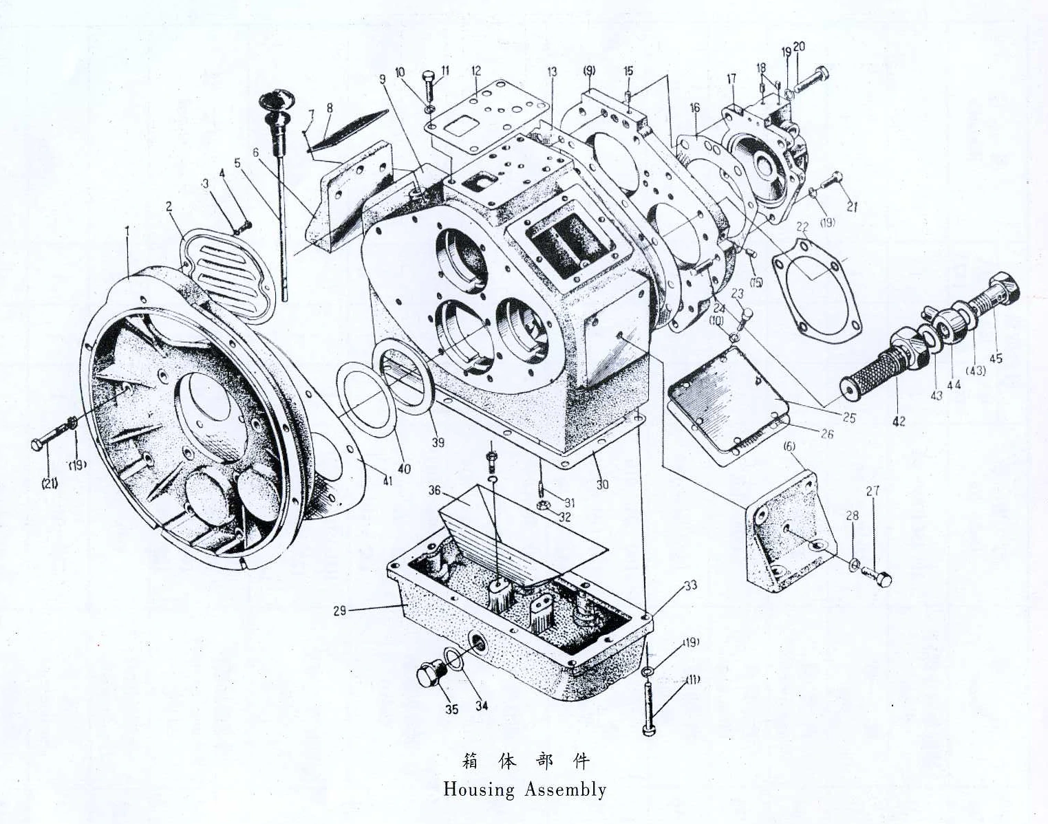
No. | Part Name | Part No. | Qty. | Remarks |
| 1 | Front cover | 142 – 04 – 008 | 1 | for no bell housing |
| 2 | Bell housing | 142 – 04 – 008X1 142 – 04 – 008X2 | 1 | SAE No2SAE No3 Available according to order |
| 3 | Cover | 0601A – 0018 | 1 | / |
| 4 | Spring washer | 6GB93 – 76 | 2 | / |
| 5 | Screw | M6x10GB67 – 76 | 2 | / |
| 6 | Dipstick | 142 – 04 – 200 | 1 | / |
| 7 | Supporter | 142 – 04 – 010 | 2 | / |
| 8 | Rivet | 2x4GB827 – 76 | 4 | / |
| 9 | Name plate | Q25 – 01 – 01 | 1 | / |
| 10 | Housing | 142 – 04 – 100 | 1 | / |
| 11 | Washer | B8GB97 – 76 | 8 | / |
| 12 | Bolt | M8x55GB30 – 76 | 6 | / |
| 13 | Gasket | 142 – 04 – 004 | 1 | / |
| 14 | Gasket | 142 – 04 – 001A | 1 | / |
| 15 | Plug | φ7Q21 – 25 | 2 | / |
| 16 | Gasket | 142 – 04 – 003 | 1 | / |
| 17 | End cover | 142 – 04 – 002 | 1 | / |
| 18 | End cover | 142 – 04 – 002X | 1 | for P. T. O |
| 19 | Plug | Q06 – 03 – 15 | 2 | / |
| 20 | Spring washer | 8GB93 – 76 | 30 | / |
| 21 | Bolt | M8x45GB30 – 76 | 2 | / |
| 22 | Bolt | M10x30GB30 – 76 | 21 | / |
| 23 | Gasket | 142 – 04 – 007A | 1 | / |
| 24 | Bolt | M8x12GB30 – 76 | 10 | / |
| 25 | Pin | 8x30GB118 – 76 | 2 | / |
| 26 | Side cover | 142 – 04 – 013 | 1 | / |
| 27 | Gasket | 125 – 04 – 011 | 2 | / |
| 28 | Bolt | M10x30GB30 – 76 | 10 | / |
| 29 | Spring washer | 10GB93 – 76 | 39 | / |
| 30 | Bottom cover | 125 – 04 – 005A 125 – 04 – 005Ax | 1 | X means an alternative Part for i<3:1 |
| 31 | Gasket | 125 – 04 – 004 | 1 | / |
| 32 | Screw | M625GB75 – 76 | 1 | / |
| 33 | Nut | M6GB52 – 76 | 1 | / |
| 34 | Copper washer | 22Q20 – 03 | 1 | / |
| 35 | Drain plug | Q21 – 15 | 1 | / |
| 36 | Shroud | 125 – 04 – 006 | 1 | / |
| 37 | Washer | 142 – 04 – 004 | 1 | / |
| 38 | Shim | 142 – 04 – 005 | 1-2 | / |
| 39 | Gasket | 142 – 04 – 006 142 – 04 – 006X1 | 1 | for no bell housing |
| 40 | Welding assembly of filter | 125 – 04 – 301 | 1 | 4 parts welded into one as integral |
| 41 | Copper washer | Q21-03 | 2 | / |
| 42 | Suction pipe | 125 – 04 – 302 | 1 | / |
| 43 | Connector | Q21 – 19 | 1 | / |
| ——END—— | ||||
No. | Part Name | Part No. | Qty. | Remarks |
| 1 | Handle | Q06 – 03 – 13 | 1 | / |
| 2 | Bolt | Q21 – 19 | 1 | / |
| 3 | Copper washer | 14Q20 – 03 | 2 | / |
| 4 | Bolt | M6x15GB30 – 76 | 1 | / |
| 5 | Front cover | Q06 – 03 – 05 | 1 | / |
| 6 | Gasket | Q06 – 03 – 06 | 1 | / |
| 7 | Valve body | Q06 – 03 – 01 | 1 | / |
| 8 | Spring seat | Q06 – 03 – 14 | 1 | / |
| 9 | Spring | 0.8x6x20 JB272 – 60 | 1 | / |
| 10 | Steel ball | 6GB308 – 77 | 1 | / |
| 11 | Plug | φ7Q21 – 14 | 2 | / |
| 11 | Plug | Q06 – 03 – 15 | 4 | / |
| 12 | Pin | 4x10GB879 – 76 | 1 | / |
| 13 | Shifting valve | Q06 – 03 – 02 | 1 | / |
| 14 | Control valve | Q06 – 03 – 12 | 1 | / |
| 15 | Overflow valve | Q06 – 03 – 10 | 2 | / |
| 16 | Spring | Q06 – 03 – 11 | 1 | / |
| 17 | Spring | Q06 – 03 – 09 | 1 | / |
| 18 | Washer | B8GB97 – 76 | 0 – 2 | / |
| 19 | Delay valve | Q06 – 03 – 08 | 1 | / |
| 20 | Rear cover | Q06 – 03 – 03 | 1 | / |
| 21 | Bolt | M6x12GB70 – 76 | 12 | / |
| 22 | Nut | M6GB54 – 76 | 1 | / |
| 23 | Bolt | M6x15GB30 – 76 | 1 | / |
| 24 | Gasket | Q06 – 03 – 04 | 1 | / |
| 25 | Spring | 0.5x7x50 JB272 – 60 | 1 | / |
| 26 | Steel ball | 8GB308 – 77 | 1 | / |
| 27 | Valve seat | Q06 – 03 – 07 | 1 | / |
| ——END—— | ||||

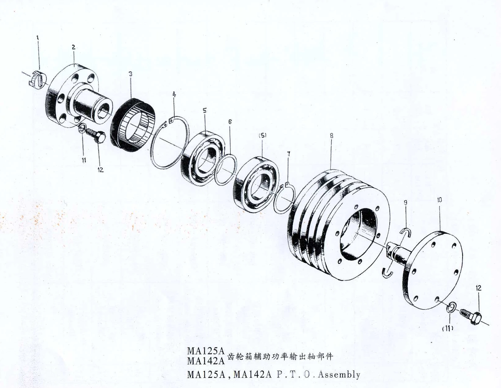
No. | Part Name | Part No. | Qty. | Remarks |
| 1 | Coupling | 125 – F1 – 007 | 1 | / |
| 2 | Bearing seat | 125 – F1 – 001 | 1 | / |
| 3 | Oil seal | SPD45x70x12 HG4 – 692 – 67 | 1 | / |
| 4 | Snap ring | 68GB893 – 76 | 1 | / |
| 5 | Bearing | 108GB276 – 82 | 2 | / |
| 6 | Spacer | 125 – F1 – 004 | 1 | / |
| 7 | Snap ring | 40GB894 – 76 | 1 | / |
| 8 | Belt wheel | 125 – F1 – 006 | 1 | / |
| 9 | Seal ring | 100 – 01 – 006 | 2 | / |
| 10 | Flange | 125 – F1 – 005 | 1 | / |
| 11 | Washer | 8GB93 – 76 | 12 | / |
| 12 | Bolt | M8x20GB21 – 76 | 12 | / |
| ——END—— | ||||
No. | Part Name | Part No. | Qty. | Remarks |
| 1 | Connector screw | Q21 – 19 | 2 | / |
| 2 | Washer | 22Q20 – 03 | 4 | / |
| 3 | Flange | Q08 – 03 – 06 | 2 | / |
| 4 | Washer | 8GB93 – 76 | 4 | / |
| 5 | Bolt | M8×20GB30 – 76 | 4 | / |
| 6 | End cover | Q08 – 03 – 01 | 2 | / |
| 7 | “O” ring | Q08 – 03 – 02 | 2 | / |
| 8 | Cooling tube assembly | Q08 – 03 – 100 | 1 | / |
| 9 | Connecting plate | Q08 – 03 – 04 | 1 | / |
| 10 | Bolt | M6 25GB30 – 76 | 4 | / |
| 11 | Washer | 6GB93 – 76 | 12 | / |
| 12 | Housing | Q08 – 03 – 03 | 1 | / |
| 13 | Bolt | M6×40GB900 – 76 | 8 | / |
| ——END—— | ||||

Note: All Above Data are Just for Reference, All Data Might Change Without Notices or Updates, Please Contact Our Sales Team to Confirm All Details Via WhatsApp or Email.

Engine Sale Manual

Installation Drawing

Installation Manual

Operation Manual

Parts Catalogue

Report & Certifcate
Tags: